In the iron and steel smelting industry, arc furnaces serve as the core equipment for steelmaking. While their large-scale and ultra-high-power development has improved production efficiency, their asymmetric, time-varying, and nonlinear load characteristics have led to severe fluctuations in reactive power of power supply lines, causing issues such as voltage flicker and increased line losses, which seriously threaten grid stability and production continuity. As a key solution to such problems, reactive power compensation technology can real-time offset reactive power fluctuations and optimize power quality by building a fast-response compensation system. Based on professional technical literature, this article explains the core principles, control system design, and application logic of reactive power compensation for arc furnace power supply lines, guiding enterprises to ensure the stable operation of arc furnaces.

I. Core Pain Points of Arc Furnace Power Supply: Why Reactive Power Compensation Is Essential?
During the melting period of arc furnaces, frequent changes in three-phase impedance lead to multiple power quality issues in power supply lines, and reactive power compensation is the targeted solution:
1. Severe Reactive Power Fluctuations: Reactive Power Compensation Is Needed for Real-Time Offset
The arc current of arc furnaces is random, resulting in significant short-term fluctuations in reactive power (fluctuation frequency up to 10-50Hz). Without timely compensation, this can cause frequent grid voltage flicker (a voltage variation range of up to ±10%), which interferes with the normal operation of precision control equipment (such as PLCs and sensors) in the plant area and may even trigger shutdowns of surrounding production lines, resulting in economic losses. However, reactive power compensation systems can dynamically adjust output to real-time offset reactive power fluctuations and stabilize grid voltage.
2. Three-Phase Current Asymmetry: Reactive Power Compensation Is Needed for Load Balancing
The nonlinear load characteristics of arc furnaces generate a large amount of negative sequence current (accounting for 15%-20%), leading to severe three-phase current asymmetry. This further increases losses in transformers and transmission lines (loss increase up to 10%-15%) and accelerates the aging of equipment insulation. Through special circuit topology and control algorithms, reactive power compensation can effectively balance three-phase loads, reduce the impact of negative sequence current, and extend equipment service life.
3. Harmonic Pollution: Reactive Power Compensation Is Needed for Collaborative Filtering
Arc current contains multiple harmonics such as the 3rd, 5th, and 7th orders. If directly injected into the grid, these harmonics may interfere with relay protection systems and even trigger resonance accidents. In reactive power compensation systems, compensators and filters work collaboratively to not only offset reactive power but also absorb harmonic currents, controlling the total harmonic distortion rate of the grid within the range allowed by national standards (≤5%) and improving grid compatibility.
II. Principles of Reactive Power Compensation for Arc Furnace Power Supply Lines: Building a Fast-Response Compensation Network
The core goal of reactive power compensation for arc furnace power supply lines is to make the compensator a quickly controllable reactive power network. Through a parallel topology of fixed capacitors and Thyristor-Controlled Reactors (TCR), precise regulation of reactive power is achieved. The specific principles are as follows:
1. Compensator Topology: Collaborative Logic of Capacitors and TCR
The reactive power compensation system adopts a parallel structure of "Fixed Capacitors (FC) + Thyristor-Controlled Reactors (TCR)":
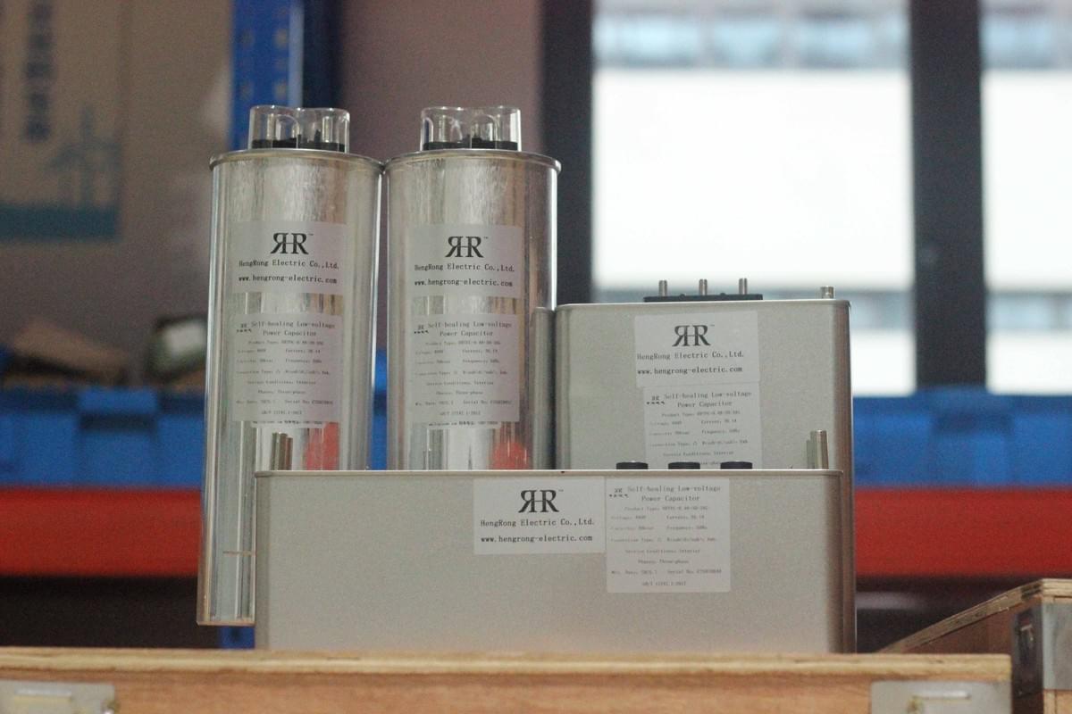
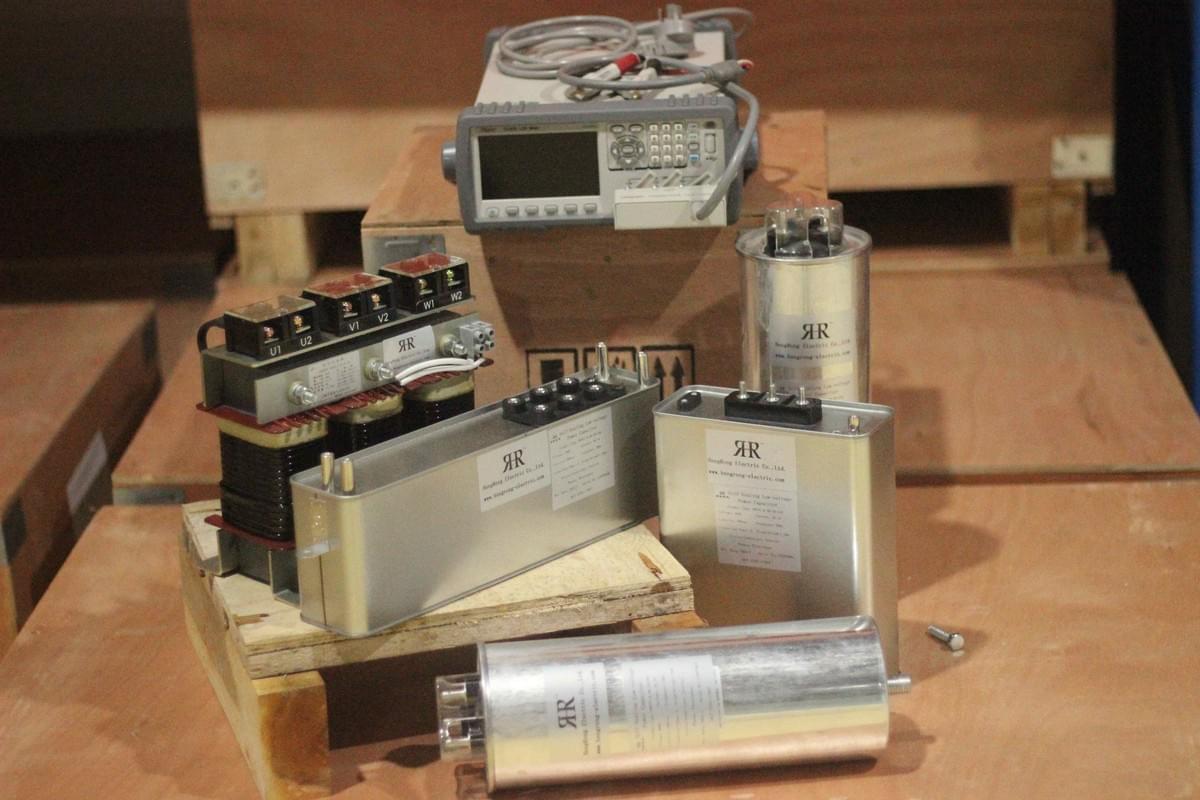
- Fixed Capacitors (FC): A three-phase capacitor bank connected in delta configuration provides basic capacitive reactive power to offset the steady-state reactive power demand of the arc furnace and reduce the adjustment burden of the TCR;
- Thyristor-Controlled Reactors (TCR): Connected in parallel with the FC, the TCR changes the output of inductive reactive power by adjusting the thyristor firing angle (α')—the smaller the firing angle, the greater the inductive reactive power; the larger the firing angle, the smaller the inductive reactive power.
When working collaboratively, the FC outputs a fixed capacitive current, and the TCR outputs an adjustable inductive current. The combination of these two currents results in a continuously adjustable compensation current, which can real-time track the reactive power changes of the arc furnace and ensure the stability of reactive power in the power supply line.
2. Compensation Rules: Deriving the Relationship Between Compensation Current and Reactive Power
To achieve the reactive power compensation goal, it is necessary to derive the relationship between compensation current and the reactive power of the arc furnace load using the symmetrical component method and the concept of complex power. Assuming the power supply line voltage is a symmetrical three-phase voltage (Phase A voltage is V, Phase B voltage is a²V, Phase C voltage is aV, where a is e^(-j2π/3)), and the reactive powers of Phases A, B, and C of the arc furnace are Qa, Qb, and Qc respectively, the required compensation current for each phase of the compensator can be described as:
- Compensation current between Phases A and B: Equal to (Reactive power of Phase A + Reactive power of Phase B - Reactive power of Phase C) divided by (√3 multiplied by voltage V);
- Compensation current between Phases B and C: Equal to (Reactive power of Phase B + Reactive power of Phase C - Reactive power of Phase A) divided by (√3 multiplied by voltage V);
- Compensation current between Phases C and A: Equal to (Reactive power of Phase C + Reactive power of Phase A - Reactive power of Phase B) divided by (√3 multiplied by voltage V).
These relationships are the core basis for the design of reactive power compensation systems, ensuring that the compensation current can accurately match the reactive power demand of the load and achieve efficient offset of reactive power.

III. Reactive Power Compensation Control System for Arc Furnace Power Supply Lines: Four-core Links Ensuring Precision
Based on the above reactive power compensation rules, the control system needs to have the capabilities of "fast detection, precise calculation, real-time triggering, and closed-loop correction". It consists of four core links to ensure compensation response speed and precision:
1. Reactive Power Detection Link: Real-Time Capture of Load Reactive Power Demand
As the "perception center" of reactive power compensation, this link collects voltage and current signals of each phase of the arc furnace through voltage and current sensors, constructs a detection circuit using solid-state components, and combines differentiation and multiplication operations to real-time calculate the reactive power of each phase (reactive power is equal to the product of voltage, current, and the sine of the phase difference between them, where the phase difference is the angle between voltage and current). The detection link needs to filter out harmonic components in the arc current, ensuring that the reactive power detection error is ≤2% and the response time is ≤1ms, providing reliable data for subsequent compensation calculations.
2. Reactor Current Calculation Link: Determining the TCR Regulation Target
Based on the load reactive power output by the reactive power detection link and combined with the reactive power compensation rule expressions, the effective value of the required compensation current is calculated. Then, according to the relationship "Effective value of compensation current = Current of fixed capacitor - Current of TCR", the effective value of the fundamental current that the TCR should output is derived in reverse. This link needs to ensure calculation precision to avoid under-compensation or over-compensation due to calculation deviations.
3. Nonlinear Conversion Link: Converting to Thyristor Firing Angle
The inductive reactive power output of the TCR is controlled by the thyristor firing angle (α'). Therefore, the reactive power compensation control system needs to convert the calculated fundamental current of the TCR into the corresponding firing angle through a nonlinear conversion algorithm. The calculation relationship of the firing angle can be described as: The fundamental current of the TCR is equal to (voltage V divided by the product of power supply angular frequency and reactor inductance) multiplied by (1 minus 2 times the firing angle divided by π, minus the sine of twice the firing angle divided by π) (where the power supply angular frequency is ω and the reactor inductance is L). The conversion precision needs to reach ±1° to ensure that the TCR can accurately respond to reactive power regulation demands.
4. Gate Pulse Generation Link: Controlling the Thyristor Conduction Timing
This link generates the corresponding thyristor triggering pulses based on the converted firing angle (α'), ensuring that the thyristors conduct at specific phases of the grid voltage to achieve precise regulation of the TCR's inductive reactive power. At the same time, the system needs to introduce reset signals and zero-crossing detection functions to avoid false triggering of pulses and ensure the stable operation of the reactive power compensation system. In addition, to improve reliability, the control system also needs to add a current closed loop to correct deviations through the TCR current feedback signal, ensuring compensation precision.

IV. Practical Value of Reactive Power Compensation for Arc Furnace Power Supply Lines: Three Core Benefits
Through the implementation of the above reactive power compensation principles and control systems, the arc furnace power supply lines can achieve significant performance improvements and economic benefits, which are reflected in the following three aspects:
1. Improving Power Supply Stability and Suppressing Voltage Flicker
The reactive power compensation system has a fast response speed (up to 5.6ms), which can real-time offset the reactive power fluctuations of the arc furnace. It reduces the voltage flicker value (short-term flicker Pst) from the over-standard range (e.g., 2.5) to the value allowed by national standards (≤1.0), avoiding equipment malfunctions and production line shutdowns caused by voltage fluctuations and improving production continuity.
2. Optimizing Power Factor and Reducing Electricity Costs
Reactive power compensation can increase the power factor of the arc furnace power supply line from 0.7-0.8 to above 0.95. This not only avoids electricity fee fines caused by low power factors but also reduces the capacity occupation of power transformation and distribution equipment (such as transformers and distribution cabinets), lowering basic electricity fee expenditures. The annual cost savings can reach hundreds of thousands of RMB.
3. Reducing Line Losses and Extending Equipment Service Life
By balancing three-phase loads and reducing negative sequence current through reactive power compensation, transmission line losses can be reduced by 10%-15%. At the same time, it lowers the transformer temperature rise (e.g., from 60K to 52K), extends the insulation life of equipment, and reduces operation and maintenance costs as well as equipment replacement investments.
V. Conclusion: Reactive Power Compensation — The Core Guarantee for Efficient Power Supply of Arc Furnaces
Under the development trend of large-scale and ultra-high-power arc furnaces, reactive power compensation technology has become the key to solving their power supply problems. By building a compensation network of "fixed capacitors + TCR" and combining it with a fast-response control system, precise regulation of reactive power can be achieved, effectively suppressing voltage flicker, optimizing power factor, and reducing line losses.

If your company is facing problems such as unstable power supply and substandard power quality in arc furnaces, please leave us a message with parameters such as arc furnace capacity and grid voltage level. Hengrong Electric CO., LTD. will use our professional reactive power compensation technology to tailor a solution for you!
