In the landscape of "power cores" for industrial production, electric motors have always played an irreplaceable role. From the transmission systems of assembly lines to the drive cores of new energy equipment, from the stable operation of large wind turbines to the precise control of precision machine tools, motor performance directly determines production efficiency, energy consumption levels, and equipment reliability. With the advancement of the "dual carbon" goals and the upgrading of Industry 4.0, the market’s demand for "high efficiency, miniaturization, and stability" of motors has become increasingly urgent—and the "combined rotor motor driven by an inverter" is precisely an innovative product in the motor field in recent years to meet this demand.
However, this "potential" motor, which combines "high torque density" and "high saliency ratio", has encountered a critical bottleneck in practical applications: during open-loop no-load start-up powered by an inverter, severe oscillations occur as the frequency increases, even triggering overcurrent protection, which seriously restricts its industrial application. Fortunately, a research team led by Dr. Chen Xuezhen and Professor Gu Chenglin from Huangshi Institute of Technology and Huazhong University of Science and Technology found a "simple, economical, and efficient" solution through small-signal model analysis and experimental verification—adding a mechanical inertial damper to the rotor shaft. This successfully resolved the oscillation issue and truly realized the performance advantages of the combined rotor motor.
I. Combined Rotor Motor: A "Golden Combination" of Two High-Performance Rotors
To understand why the combined rotor motor is highly anticipated, it is first necessary to break down the core logic of its "combination"—it integrates two complementary rotor technologies to achieve a "1+1>2" performance breakthrough.
1. ALA Rotor: The "High Saliency Expert" of Synchronous Reluctance Motors
The first part of the combined rotor is the "Axially Laminated Anisotropic (ALA) rotor". This rotor has a distinctive structure: it is formed by alternately laminating high-magnetic-conductivity materials and non-magnetic insulating materials along the axial direction at high density, much like the rotor being "cloaked in a regularly arranged magnetic-conducting armor". Its core advantage lies in its extremely high "saliency ratio" (the ratio of direct-axis inductance \(L_d\) to quadrature-axis inductance \(L_q\); for the prototype in the document, \(L_d = 108.8 \, \text{mH}\), \(L_q = 48.6 \, \text{mH}\), giving a saliency ratio of approximately 2.24) .
What does a high saliency ratio mean? For synchronous reluctance motors, a higher saliency ratio indicates a stronger ability to utilize "reluctance torque"—reluctance torque does not rely on permanent magnets and is generated solely through the difference in magnetic reluctance of the magnetic field in different directions. This enables the motor to have more stable output characteristics under medium and low-speed operating conditions, with a relatively simple structure and controllable costs.
2. Permanent Magnet Rotor: The "Torque Champion" of High-Efficiency Motors
The other part of the combined rotor is the "Surface-Mounted Permanent Magnet (SPM) rotor". The advantages of permanent magnet motors have long been recognized in the industrial sector: relying on the constant magnetic field generated by permanent magnets, they achieve a three-fold breakthrough in "high torque density, high efficiency, and high power factor"—under the same volume, the output torque of permanent magnet motors is more than 30% higher than that of traditional motors; no additional excitation current is required during operation, significantly reducing energy consumption; the power factor is close to 1, which can reduce reactive power loss in the power grid and lighten the load on the power distribution system.
3. Combined Rotor: An Innovation Balancing Performance and Practicality
Individually, ALA rotor motors excel at utilizing reluctance torque, with low costs but limited torque density; permanent magnet rotor motors have strong torque and high efficiency but impose stricter requirements on operational stability. The "ALA + SPM" combined rotor design aims to leverage the strengths of both while mitigating their weaknesses: it retains the high saliency ratio advantage of the ALA rotor to enhance stability at medium and low speeds, and utilizes the high torque density of the permanent magnet rotor to improve the overall output capability of the motor.
The document mentions that this combined design "has the potential to achieve better operating performance", and the research team has verified its feasibility through previous work (such as the optimization of motor structure and parameters in Reference [14]) . However, when this "potential" motor is paired with an inverter, a tricky issue emerges—start-up oscillations.
II. A Tricky Dilemma: Why Variable-Frequency Start-Up Oscillations Become a "Stumbling Block"
Inverters serve as the "brain" of modern motor control systems, enabling smooth speed regulation and energy-saving operation of motors by adjusting the output frequency and voltage (V/f control). However, for combined rotor motors, open-loop no-load start-up powered by an inverter has become a "performance failure scenario".
1. Experimental Insight: The True Manifestation of Oscillation Phenomena
To understand the nature of the problem, the research team built a rigorous experimental platform: a 4-pole combined rotor motor prototype with a rated power of 2.2 kW, rated phase voltage of 220 V, and pole pair number of 2 was used, powered by a Panasonic M1X374BSA general-purpose inverter. The constant voltage-to-frequency (V/f) control mode was set, outputting SPWM modulated waves (triangular carrier frequency of 8 kHz), and the motor’s operating data was recorded through manual frequency raising.
The experimental results were worrying: when the inverter output frequency was low (5 Hz, 10 Hz), the motor speed could stably follow the synchronous speed (150 rpm, 300 rpm), with phase currents of 3.9 A and 2.9 A respectively, ensuring stable operation; however, as the frequency increased, the situation gradually spiraled out of control—at 15 Hz, the speed fluctuation range expanded to 430–481 rpm, with a current fluctuation of 3.3–4.2 A; at 35 Hz, the speed fluctuation reached 963–1059 rpm, and the current soared to 6.4–7.3 A; when the frequency reached 41 Hz, the motor directly triggered the inverter’s overcurrent protection and could not continue operating .
This set of data clearly shows that as the power supply frequency increases, the oscillations of the combined rotor motor become increasingly severe, eventually leading to shutdown due to excessive current. For industrial scenarios requiring high-frequency operation (such as high-speed speed regulation of fans and water pumps), such oscillations not only affect production continuity but also may cause overheating of the motor windings and wear of mechanical components, significantly shortening the equipment lifespan.
2. Hazards of Oscillations: A Chain Reaction from Equipment Protection to Production Efficiency
In industrial production, the "start-up stability" of motors is directly related to the safety of the entire production line. Frequent oscillations of the combined rotor motor during start-up can trigger a series of chain problems:
- Equipment Damage Risk: Severe oscillations increase the mechanical stress on the motor shafting, leading to premature wear of components such as bearings and couplings; at the same time, current fluctuations intensify copper loss in the windings, causing the motor temperature to rise, accelerating insulation aging, and increasing the risk of motor burnout.
- Production Interruption Loss: After the inverter’s overcurrent protection is triggered, the motor shuts down, and the production line is forced to pause—for continuous production industries such as automobile manufacturing and electronic component processing, each minute of shutdown may result in economic losses of tens of thousands of yuan.
- Hidden Increase in Energy Consumption: During oscillations, the output torque of the motor is unstable. To maintain load operation, the inverter needs to frequently adjust the output power, leading to a decrease in electrical energy conversion efficiency and an invisible increase in the enterprise’s electricity costs.
Faced with this dilemma, the research team did not stop at "describing phenomena" but used the "small-signal model"—a "technical microscope"—to deeply dissect the physical nature behind the oscillations.
III. Tracing the Root Cause: The "Counterforce" of Negative Electromagnetic Damping Coefficient
Motor oscillations are not a new phenomenon, but why are the oscillations of combined rotor motors so special? Using the "small-signal linearization method", the research team converted the motor’s dynamic operating process into a quantifiable mathematical model and finally identified the "culprit"—the negative electromagnetic damping coefficient.
1. Small-Signal Model: A "Microscope" for Dissecting Motor Oscillations
To analyze the dynamic stability of the motor, it is first necessary to establish a mathematical model that can reflect "small disturbances". The research team proposed three reasonable assumptions to simplify the analysis process:
- Ignoring the saturation effect of the motor iron core to avoid complex calculations caused by the nonlinearity of magnetic parameters;
- Assuming the SPM segment (permanent magnet rotor part) is isotropic, i.e., its direct-axis and quadrature-axis inductances are equal;
- Ignoring the magnetic leakage between the ALA segment and the SPM segment to ensure the accuracy of flux linkage calculations.
Under these assumptions, the research team introduced the concept of "small rotor position disturbance": when the motor is operating in a steady state, if subjected to small disturbances (such as frequency fluctuations, load changes), the rotor position will produce a small increment \(\Delta \theta = \Delta \theta_m \sin(\alpha t)\) (where \(\Delta \theta_m\) is the amplitude of the small disturbance, and \(\alpha\) is the oscillation angular frequency of the motor). By substituting this disturbance into the motor’s voltage equation, torque equation, and motion equation, the fluctuation component \(\Delta T_e\) of the electromagnetic torque was finally derived .
2. Electromagnetic Damping Coefficient: The "Invisible Brake" for Motor Stability
In the dynamic balance of the motor, "damping" is the key to maintaining stability—much like the brake system of a car, the greater the damping, the easier it is for the vehicle to stabilize when encountering bumps. The damping of the motor is divided into two parts:
- Mechanical Viscous Damping (\(k_B\)): Derived from friction in the motor bearings, air resistance, etc., it is a "naturally existing" damping that is always positive and plays a role in suppressing oscillations;
- Electromagnetic Damping (\(k_d\)): Damping generated by electromagnetic induction inside the motor, whose positive or negative directly determines its role in "suppressing" or "promoting" oscillations.
Through derivation, the research team found that the fluctuation component of the electromagnetic torque can be expressed as \(\Delta T_e = k_s \Delta \theta - k_d \Delta \omega_r\) (where \(k_s\) is the synchronous torque coefficient, and \(\Delta \omega_r\) is the rotor angular speed disturbance). The physical meaning of \(k_d\) (electromagnetic damping coefficient) is: when the rotor has an angular speed disturbance, the electromagnetic system will generate a torque that "resists the disturbance"—if \(k_d\) is positive, this torque will suppress oscillations and return the motor to stability; if \(k_d\) is negative, this torque will "promote" the disturbance, making the oscillations increasingly severe.
3. Negative Damping: The "Hidden Driver" of Intensified Oscillations
By combining the motor’s voltage equation, torque equation, and motion equation, the research team derived the key condition for system stability: \(k_B + k_d > 0\). In other words, only when the "combined force" of mechanical damping and electromagnetic damping is positive can the motor suppress oscillations and maintain stability; if \(k_B + k_d \leq 0\), the motor will either experience constant-amplitude oscillations (\(k_B + k_d = 0\)) or asynchronous oscillations with increasing amplitude (\(k_B + k_d < 0\)) .
To verify this conclusion, the research team plotted a graph of "the relationship between electromagnetic damping coefficient \(k_d\) and operating frequency \(f\)" (Figure 3). The results showed that \(k_d\) exhibits a trend of "first positive, then negative, and finally rising" as the frequency increases—when the frequency is low (e.g., 5–10 Hz), \(k_d\) is positive, and mechanical damping and electromagnetic damping jointly suppress oscillations, ensuring stable motor operation; when the frequency increases to a certain range (e.g., 15–35 Hz), \(k_d\) becomes negative and gradually drops to a minimum value. At this point, even with the "effort" of mechanical damping, the combined force of the two remains negative, leading to increasingly severe oscillations; when the frequency continues to increase (approaching 50 Hz), \(k_d\) rebounds but may still remain at a low level, unable to fully offset the impact of negative damping .
This finding completely solved the mystery of the combined rotor motor’s oscillations: within a specific frequency range, the electromagnetic damping coefficient \(k_d\) becomes negative, and its role in "promoting" oscillations exceeds the "suppressing" role of mechanical damping, ultimately leading to intensified motor oscillations and even overcurrent shutdown.
IV. A Solution: The "Stabilizing Magic" of Mechanical Inertial Dampers
After identifying the root cause of the problem, the idea for a solution gradually became clear: since negative electromagnetic damping is the "culprit", can we compensate for the "counterforce" of negative electromagnetic damping by increasing mechanical damping? The research team proposed a bold and practical solution—adding a "mechanical inertial damper" to the rotor shaft.
1. Design Concept of the Damper: Compensating Negative Electromagnetic Damping with Mechanical Damping
The core design logic of the mechanical inertial damper is simple: by installing an "inertia disk + viscous damping structure" on the motor rotor shaft (non-output end, to avoid affecting load transmission), the total damping coefficient and moment of inertia of the system are increased, thereby making the combined force of "mechanical damping + electromagnetic damping" positive again and suppressing oscillations.
Specifically, this damper has two key functions:
- Supplementing Mechanical Damping: The "viscous damping coefficient (\(T_{dd}\))" of the damper can directly increase the mechanical viscous damping (\(k_B\)) of the system, equivalent to adding a set of "powerful brakes" to the motor to offset the impact of negative electromagnetic damping;
- Stabilizing Speed Fluctuations: The "inertia disk moment of inertia (\(J_d\))" of the damper can increase the moment of inertia (\(J\)) of the system, making the motor’s speed change more gently when encountering disturbances, reducing the amplitude of angular speed disturbance (\(\Delta \omega_r\)) and minimizing oscillation risks at the source.
2. The Art of Balancing Key Parameters: The "Golden Ratio" of \(T_{dd}\) and \(J_d\)
The effect of the damper is not "the larger the parameter, the better". Through eigenvalue analysis of the small-signal model, the research team found that \(T_{dd}\) (viscous damping coefficient) and \(J_d\) (inertia disk moment of inertia) need to be precisely matched to achieve a balance between "stability and dynamic performance".
(1) Viscous Damping Coefficient (\(T_{dd}\)): Neither Too Small nor Too Large
To verify the impact of \(T_{dd}\), the research team fixed \(J_d = 0.02 \, \text{kg·m}^2\) and plotted a graph of "load torque (\(T_L\)) versus system eigenvalues" under different \(T_{dd}\) values (Figure 5):
- When \(T_{dd}\) is too small (e.g., 0.07 N·m·s/rad), the total damping of the system is still insufficient. Even under a relatively low load (e.g., 20 N·m), the real part of the eigenvalue may become positive, leading to motor instability;
- When \(T_{dd}\) is too large (e.g., 0.8 N·m·s/rad), although system stability is improved, the dynamic response of the motor slows down—much like a car with overly hard brakes, which becomes "sluggish" during acceleration, affecting the motor’s speed regulation performance;
- When \(T_{dd} = 0.2 \, \text{N·m·s/rad}\), the real parts of the eigenvalues of the system are negative within the range of \(T_L < 29 \, \text{N·m}\), ensuring both stable operation and good dynamic response .
(2) Inertia Disk Moment of Inertia (\(J_d\)): Balancing Stability and Dynamic Performance
Similarly, the research team fixed \(T_{dd} = 0.2 \, \text{N·m·s/rad}\) and analyzed the impact of \(J_d\) on system performance (Figure 6):
- When \(J_d\) is too small (e.g., 0.008 kg·m²), the moment of inertia of the system is insufficient, resulting in weak "resistance" to speed disturbances. Minor disturbances may trigger oscillations;
- When \(J_d\) is too large (e.g., 0.07 kg·m²), the moment of inertia of the system is excessively large, leading to strong "inertia" of the motor. The speed response lags behind when adjusting the frequency, deteriorating dynamic performance;
- When \(J_d = 0.02 \, \text{kg·m}^2\), the system can effectively suppress disturbances while quickly responding to frequency changes, achieving the optimal balance between "stability and dynamics" .
3. Verification via Small-Signal Model: How the Damper Stabilizes the System
To further verify the effectiveness of the damper, the research team compared the system stability with and without the damper (Figures 4 and 5):
- Without the damper, the motor was unstable under light loads (e.g., \(T_L < 5 \, \text{N·m}\)) and heavy loads (\(T_L > 16 \, \text{N·m}\)), and could only operate within a narrow intermediate load range (5–16 N·m);
- With the damper (\(J_d = 0.02 \, \text{kg·m}^2\), \(T_{dd} = 0.2 \, \text{N·m·s/rad}\)), the motor could operate stably within the range of \(T_L < 29 \, \text{N·m}\), expanding the load adaptation range by nearly double .
This result proves that by optimizing the parameters of the mechanical inertial damper, the impact of negative electromagnetic damping can be completely compensated, significantly expanding the stable operating range of the combined rotor motor.
V. Evidence Speaks: Experimental Data Witnessing Performance Leaps
No matter how perfect the theoretical analysis is, it requires experimental verification. Through "start-up performance experiments" and "load performance experiments", the research team used real data to demonstrate the "magic" of the mechanical inertial damper.
1. Transformation of Start-Up Performance: From "Severe Oscillations" to "Smooth Speed Rise"
The start-up experiment adopted the "automatic frequency raising" mode, setting the inverter to gradually increase the frequency from 0 Hz to the rated frequency of 50 Hz, and monitoring the motor’s speed curve using an oscilloscope (Figure 7). The results were surprising:
- Without the damper, the motor showed obvious speed fluctuations when the frequency exceeded 15 Hz, with a fluctuation amplitude of over 100 rpm after 35 Hz, and triggered overcurrent protection at 41 Hz;
- With the damper, the motor’s speed curve showed an almost smooth upward straight line throughout the process of increasing the frequency from 0 Hz to 50 Hz, with no obvious oscillations, and finally stabilized at the rated speed of 1500 rpm (for a 4-pole motor, the synchronous speed corresponding to 50 Hz is 1500 rpm) .
This means that the mechanical inertial damper completely solves the variable-frequency start-up oscillation problem of the combined rotor motor, enabling the motor to achieve a start-up process with "no oscillations, no protection, and smooth speed rise"—for industrial scenarios requiring frequent start-ups and shutdowns (such as machine tools and conveyor lines), this improvement directly eliminates the risk of "start-up failure".
2. Breakthrough in Load Capacity: The Production Value Behind Increased Power
Stable start-up is only the first step; the core value of a motor lies in its "load-carrying capacity". The research team built a "load performance experimental platform": the combined rotor motor with the damper was used to drive a DC motor, and the load size was adjusted by adjusting a sliding resistor box. The output voltage (U) and current (I) of the DC motor were measured to calculate the motor’s electromagnetic power \(P_{em}\) (\(P_{em} = P_0 + P_{cu} + P_L\), where \(P_0\) is the no-load torque power, \(P_{cu}\) is the copper loss, and \(P_L\) is the load power) .
The experimental data (Table 2) showed a significant performance improvement:
- At 899 rpm, the electromagnetic power \(P_{em}\) of the motor with the damper was 1779.5 W, while that of the motor without the damper was only 683.2 W, representing a power increase of 160%;
- At 1049 rpm, \(P_{em}\) of the motor with the damper was 2021.1 W, compared to 914.8 W for the motor without the damper, an increase of 121%;
- At 1198 rpm, \(P_{em}\) of the motor with the damper was 2320.4 W, versus 1156.1 W for the motor without the damper, an increase of 101% .
More importantly, the motor without the damper "could only operate at low speeds", while the motor with the damper could stably carry loads at higher speeds—this means that the "high-efficiency range" of the combined rotor motor has been significantly expanded, allowing the motor to cover medium and high-speed operating conditions instead of being limited to low-speed scenarios, and expanding its application scope from "a single field" to "multi-scenario adaptation".
VI. Small Modifications Driving Great Benefits: Industrial Empowerment of Mechanical Inertial Dampers
The improvement of the combined rotor motor seems to be just "adding a damper to the rotor shaft", but the industrial value behind it is immeasurable. For enterprises, this technology brings not only "improved motor performance" but also a triple optimization of "cost, efficiency, and reliability".
1. Cost Advantage: A More Economical Solution Than Complex Electronic Control
There is more than one way to solve motor oscillations. Traditional solutions usually involve "upgrading the control system": for example, adding sensors (such as encoders) to achieve closed-loop control, modifying the inverter program to optimize the V/f curve, or even replacing the inverter with a higher-performance one. However, these solutions are extremely costly:
- Adding an encoder and a closed-loop control system increases the modification cost of a single motor by several thousand yuan;
- Customizing the inverter program requires a professional team, has a long R&D cycle, and is difficult to adapt to different motor models;
- Replacing the inverter with a higher-performance one costs 2–3 times that of an ordinary inverter.
In contrast, the mechanical inertial damper has the advantage of being "simple and economical":
- It has a simple structure, consisting only of an inertia disk and viscous damping components, resulting in low manufacturing costs;
- It is easy to install, requiring no modifications to the internal structure of the motor—only installation on the non-output end of the rotor shaft, resulting in low labor costs;
- Parameter debugging is simple: after determining the optimal \(T_{dd}\) and \(J_d\) through experiments, batch replication is possible without personalized customization.
For small and medium-sized enterprises, this "low-cost, easy-to-implement" solution is undoubtedly the "most cost-effective" choice—achieving a stability effect comparable to that of high-end electronic control solutions at a fraction of the cost.
2. Expansion of Application Scenarios: Full Adaptation from Low to High Speeds
Before adding the damper, the combined rotor motor was limited to low-speed, light-load scenarios (such as small fans and micro-conveyor lines) due to the "high-frequency oscillation" problem. After adding the damper, its application scenarios have been completely expanded:
- Medium and High-Speed Transmission Scenarios: Such as the spindle drive of CNC machine tools (requiring a stable speed of 1000–3000 rpm) and the speed-regulatied-regulating operation of large water pumps (requiring stable load carrying at the rated frequency of 50 Hz);
- Heavy-Load Start-Up Scenarios: Such as crushers, compressors, and other equipment requiring "high-torque start-up". With the damper, the motor can stably output torque during start-up, avoiding start-up failure caused by oscillations;
- Frequent Start-Up and Shutdown Scenarios: Such as the conveyor motors of automated production lines, which need to start and shut down dozens of times a day. The damper ensures smooth, oscillation-free start-up each time, extending the equipment lifespan.
Taking the water pump system of a sewage treatment plant as an example: traditionally, ordinary induction motors were used, which had high energy consumption and a narrow speed regulation range; if replaced with a combined rotor motor with a damper, energy consumption can be reduced by 15%–20%, and stable operation can be achieved within the frequency range of 20–50 Hz to adapt to the sewage treatment volume requirements at different times, saving hundreds of thousands of yuan in electricity costs annually.
3. Green Benefits: Low-Carbon Value of Promoting Efficient Motor Operation
Under the "dual carbon" goals, the "energy efficiency" of motors has become a core indicator of enterprise concern. The combined rotor motor itself has the "high-efficiency" gene (permanent magnets reduce excitation loss, and the ALA rotor improves the utilization rate of reluctance torque), and the addition of the mechanical inertial damper further releases its energy efficiency potential:
- Reducing oscillation losses: Without the damper, oscillations cause current fluctuations, increasing copper loss by 10%–15%; with the damper, the current is stable, significantly reducing copper loss;
- Expanding the high-efficiency range: The high-efficiency range of the combined rotor motor was originally concentrated in the low-speed segment; after adding the damper, the high-efficiency range extends to the medium and high-speed segments, allowing the motor to operate in the high-efficiency zone under more operating conditions;
- Reducing equipment energy consumption: Stable operating conditions reduce the "frequent adjustments" of the inverter, lowering the inverter’s own losses and further improving the energy efficiency of the entire drive system.
It is estimated that if 10% of ordinary motors in the industrial sector are replaced with "combined rotor motors with dampers", millions of tons of carbon emissions can be reduced annually, providing important support for the low-carbon transformation of industry.
VII. Technological Innovation Illuminating the Future of High-Efficiency Motors: From Laboratory to Industry
The research conducted by the team led by Dr. Chen Xuezhen and Professor Gu Chenglin not only solved the start-up oscillation problem of the combined rotor motor but also provided a new approach for "stability optimization" in the motor field—when complex electronic control solutions are difficult to implement, returning to the optimization of mechanical structures may lead to a "low-cost, high-reliability" solution.
The significance of this research is reflected in three aspects:
- Theoretical Aspect: It is the first time that the "negative electromagnetic damping coefficient" has been clearly identified as the core cause of variable-frequency start-up oscillations in combined rotor motors, filling the research gap in this field;
- Technical Aspect: The proposed "mechanical inertial damper" solution provides a replicable technical path for the stability optimization of similar motors;
- Industrial Aspect: It enables the combined rotor motor to move from a "laboratory prototype" to "industrial application", providing enterprises with a "high-efficiency, stable, and economical" motor option.
In the future, with in-depth research on the optimization of damper parameters (such as the adoption of intelligently adjustable variable dampers) and further improvements in the structure of the combined rotor motor (such as optimizing the lamination ratio of ALA and SPM), the performance of this motor will continue to improve. There is reason to believe that in fields such as industrial automation, new energy, and intelligent manufacturing, the "combined rotor motor with a damper" will become a new generation of "power stars", injecting strong momentum into industrial upgrading.
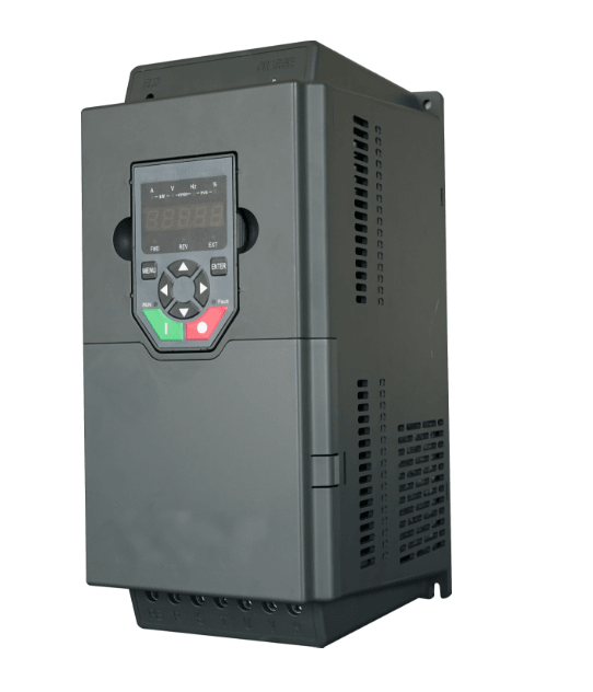
From the "oscillation dilemma" to "stable operation", and from "laboratory data" to "production line application", the breakthrough of this technology once again proves that truly valuable innovation not only requires profound theoretical knowledge but also practical thinking that is close to industrial needs—and this is the key to Chinese motor technology moving towards the forefront of the world.
Partner with Hengrong Electric to Explore the Global New Track of Industrial Inverters and Energy Conservation
Amid the global wave of industrial transformation towards "high efficiency, energy conservation, and green low-carbon development," inverters— 作为 the core equipment for motor drive and energy optimization—must not only meet the precise speed regulation needs of different countries and scenarios (such as adaptation to 50/60Hz power grids and compatibility with high/low-voltage working conditions) but also solve the common pain points of equipment failures and high electricity bills caused by harmonic interference. Hengrong Electric is providing one-stop solutions for industrial customers worldwide with its globally competitive products and solutions.
With years of deep cultivation in the industrial inverter field, Hengrong Electric’s inverter products not only cover a full range of 6-pulse and 12-pulse models but also achieve three core advantages through technological iteration:
First, energy efficiency: They can reduce motor energy consumption by over 30% and extend equipment lifespan by 5-8 years, making them suitable for global mainstream industrial loads such as fans, water pumps, punch presses, and conveyors.
Second, harmonic compliance: Equipped with built-in high-efficiency harmonic suppression modules, the products are strictly compliant with international harmonic standards such as IEEE 519 and IEC 61000. They reduce the generation of low-order harmonics (5th, 7th orders) from the source, meeting the power grid requirements of regions such as Europe, America, Southeast Asia, and the Middle East without the need for additional filters.
Third, stable adaptability: Supporting wide voltage input (380V-1140V) and multilingual operation interfaces, and holding international certifications including CE, UL, and TUV, the products can be seamlessly integrated into various industrial scenarios worldwide. This completely solves the problems of "equipment incompatibility" and "penalties for excessive harmonics" faced by transnational factories.
To bring high-quality inverter technology to industrial customers around the world, Hengrong Electric is now sincerely recruiting agent partners worldwide. Whether you are an industrial equipment distributor in Europe and America, a power solution provider in Southeast Asia, or a localized engineering service provider in the Middle East and Africa, we will provide comprehensive international support:
- Technical and Compliance Support: Offer multilingual technical documents (English, German, Spanish, Arabic, etc.), free training on international certifications (interpretation of CE/UL/TUV), and guidance on harmonic measurement and solution design to help agents quickly adapt to local market needs.
- Supply Chain and Pricing Support: Rely on globalized production bases and logistics networks to ensure stable supply and short-cycle delivery. Provide agents with highly competitive tiered supply prices to guarantee profit margins.
- Localized Service Support: Establish technical service centers in major global regions, offer 24/7 multilingual technical consultation and fast maintenance responses, and assist agents in solving customers’ after-sales problems.
- Marketing Support: Share resources for international exhibitions (such as Hannover Messe in Germany and Automation Fair in the US), brand promotion materials, and digital marketing tools to help agents quickly open up the local market.
The global 100-billion-level industrial inverter and energy conservation market is ushering in a boom period. Hengrong Electric looks forward to partnering with colleagues around the world—taking reliable products as the foundation and comprehensive support as the guarantee—to jointly create "cost reduction, energy conservation, and stability" value for global industrial customers and achieve win-win cooperation in the track of green industrial upgrading.
No matter which country you are in or which field you focus on, if you are optimistic about the future of industrial inverters, Hengrong Electric is willing to be your trustworthy global business partner. We look forward to your joining, and together we will empower global industry and create a sustainable future!
