
Against the backdrop of new-type power system construction, capacitors, with their flexible reactive power regulation capability, have become a "key support" for regional power grids to optimize structure, improve transmission efficiency, and ensure stability. Whether it is breaking through the capacity limit of long-distance power transmission or guaranteeing voltage stability for end-users, the quality of their application directly determines the operational performance of power grids. This article analyzes their value in empowering regional power grids from four dimensions: "synergy between capacitors and series compensation devices", "three core functions", "full-dimensional protection", and "customized solutions".
I. Capacitors: Core of Series Capacitor Compensation Devices, Reshaping Power Transmission Capacity
Series capacitor compensation devices are the core solution to address "insufficient transmission capacity and high losses" in power grids. As the functional core, capacitor banks directly determine the compensation effect through their parameter accuracy and stability.
1. Composition of Series Capacitor Compensation Devices: Centered on Capacitor Banks
The device is built around capacitor banks with three key modules:
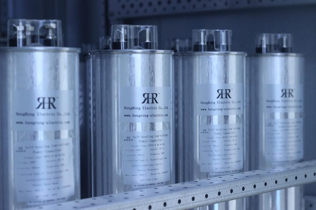
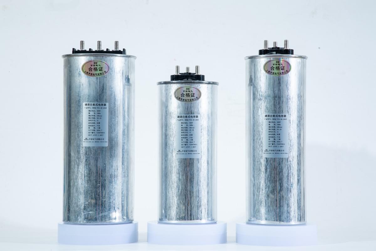
- Core Module: High-Voltage Capacitor Banks: Customized reactance values (e.g., 20-30Ω commonly used for 500kV lines) based on line voltage levels (110kV/220kV/500kV) and transmission requirements, serving as the main component for "offsetting line inductive reactance";
- Protection Module: MOV + Spark Gap: Metal Oxide Varistors (MOV) are connected in parallel to absorb overvoltage, while spark gaps act as backups to ensure capacitor safety under extreme operating conditions;
- Monitoring Module: Sensors + PLC System: Real-time collection of current, voltage, and temperature data to enable operational monitoring and abnormal alarms.
Working Principle: Capacitor banks are connected in series with transmission lines. By leveraging their capacitive reactance characteristics to offset the inductive reactance of lines, the total impedance is reduced. Taking a 200km 500kV line as an example, after configuring suitable capacitor banks, the static stability limit transmission capacity can be increased by 15%-40%, alleviating the issue of wind and solar curtailment in new energy bases.
2. Differentiated Application of Capacitor Banks
Based on load fluctuations and new energy penetration rates, compensation devices are divided into two types, with different configurations of capacitor banks:
- Fixed Type (FSC): Fixed Reactance Capacitor Banks: Suitable for stable power grids with daily load fluctuations < 10% (e.g., suburban and agricultural lines). No dynamic adjustment is required, featuring low cost and simple operation;
- Controllable Type (TCSC): Adjustable Reactance Capacitor Banks: Dynamic reactance adjustment (0-120% of rated reactance) via thyristors, with millisecond-level response to sudden load changes or new energy fluctuations. This suppresses subsynchronous resonance and prevents voltage from exceeding limits.
II. Three Core Functions of Capacitors: Ensuring Safe and Efficient Grid Operation
In the full "transmission-distribution-consumption" chain of power grids, capacitors act as "efficiency optimizers", "voltage stabilizers", and "energy savers".
1. Enhancing Transmission Stability, Breaking Capacity Limits
Extended transmission distances tend to cause "reduced power limits and expanded phase angle differences". Series capacitor banks can:
- Offset 30%-50% of line inductive reactance, reducing equivalent impedance (e.g., increasing the transmission limit of 220kV lines from 1200MW to over 1500MW);
- Narrow the phase angle difference (from 30° to within 20°), improving anti-disturbance capability.
Case of Jibei Power Grid: Series compensation devices with a compensation degree of 40%-50% were installed on 500kV new energy transmission channels. Capacitor banks increased the transmission capacity of wind power from western Inner Mongolia by 30%, adding 1.2 billion kWh of annual wind power consumption.
2. Improving Voltage Quality, Guaranteeing End-User Power Supply
End-users (industrial parks, villages) often face voltage issues due to high losses and concentrated inductive loads. Shunt capacitor banks address this through "reactive power regulation":
- Peak Load Period: Release capacitive reactive power to maintain voltage within the ±7% range specified in GB 12325-2008 (Power Quality - Supply Voltage Deviation);
- Off-Peak Load Period: Absorb excess reactive power to prevent voltage from exceeding 105% of the rated value, which could damage equipment.
Field Test in an Industrial Park: After configuring 1000kvar shunt capacitor banks on 10kV lines, voltage fluctuation was reduced from ±12% to ±5%, the failure rate of motors decreased by 40%, and annual production loss caused by voltage issues was reduced by 5 million yuan.
3. Reducing Line Losses, Improving Grid Energy Efficiency
Copper loss in transmission lines is proportional to the square of current. Capacitor banks reduce total line current (including active and reactive current) by compensating for reactive power. Taking a 220kV line with an annual transmission volume of 1 billion kWh as an example:
- Without capacitor banks: Power factor is approximately 0.85, with an annual loss of 10 million kWh;
- With capacitor banks: Power factor is increased to 0.95, reducing losses by 18% (annual loss down to 8.2 million kWh). This is equivalent to saving 600 tons of standard coal and reducing CO₂ emissions by 12,000 tons annually, delivering significant economic and environmental benefits.
III. Full-Dimensional Protection Mechanism for Capacitors: Ensuring Long-Term Reliability
In high-voltage, high-current grid environments, capacitor banks face risks such as overvoltage (e.g., lightning strikes, short-circuits), overloading (e.g., sudden increase in reactive demand), and capacitance imbalance (e.g., aging or damage of individual capacitors). A dedicated full-dimensional protection system is essential to prevent capacitor damage and grid failures.
1. Overvoltage Protection: Dual-Layer Defense
Capacitors are highly sensitive to overvoltage (exceeding 1.1 times the rated voltage), which can break down insulation and cause permanent capacitance attenuation. A "primary + backup protection" system is required:
- Primary Protection: MOV: Connected in parallel with capacitor banks. When voltage surges occur due to faults (e.g., short-circuits, lightning strikes), MOV absorbs overvoltage energy using its nonlinear volt-ampere characteristics, limiting the capacitor terminal voltage to within 1.2 times the rated value;
- Backup Protection: Spark Gap: If MOV fails due to aging or overload, the spark gap conducts in milliseconds to bypass the capacitor bank, avoiding sustained overvoltage impact.
Case of a 500kV Substation: A lightning strike caused the voltage to surge to 2.5 times the rated value. The coordinated action of MOV and spark gap controlled the capacitor voltage to within 1.15 times the rated value, resulting in no equipment damage.
2. Overload and Imbalance Protection
- Overload Protection: Current transformers monitor capacitor bank current in real-time. An alarm is triggered if the current exceeds 1.3 times the rated value for more than 1 minute; if the current rises to 1.5 times the rated value, a trip signal is sent to cut off power and prevent overheating damage;
- Imbalance Protection: Voltage differences between capacitor branches are monitored. If the voltage difference between any two branches exceeds 5%, the faulty branch is disconnected immediately to prevent fault expansion (caused by aging or internal breakdown of individual capacitors).
IV. Customized Capacitor Solutions: Full-Lifecycle Services
Tailored to grid characteristics, we provide full-lifecycle solutions centered on capacitor banks, covering "design, equipment selection, installation & commissioning, and operation & maintenance".
1. Customized Design
After on-site surveys, our engineers configure capacitor banks precisely:
- Determine rated parameters (e.g., 121kV capacitors for 110kV lines);
- Select capacitor types based on environment (metallized film capacitors for coastal areas, high-voltage ceramic capacitors for high-altitude regions);
- Match compensation devices (FSC for stable grids, TCSC for grids with high fluctuations).
2. Full-Lifecycle Services
- Early Stage: PSCAD/EMTDC simulation to optimize parameters;
- Middle Stage: Installation by teams with 10+ years of experience in compliance with GB 50227-2017 (Code for Design of Shunt Capacitor Installations), plus operation & maintenance training;
- Later Stage: Real-time monitoring via cloud platforms and quarterly on-site inspections to extend service life to over 15 years.
Conclusion: Capacitors - Core Support for New-Type Power Grids
With the growth of new energy integration and new loads, the demand for "flexible reactive power regulation" in power grids will continue to rise, and capacitors will find broader applications. We will continue to optimize capacitor performance and provide intelligent solutions integrating digital twins and AI, supporting the construction of "safe, efficient, and low-carbon" power grids. If you have needs for capacitor configuration or reactive power optimization, please contact us for customized solutions!
Facing issues like high line losses or new energy curtailment? Drop a message about your project—Hengrong Electric CO., LTD.will give you our capacitor-based solutions, which will help you solve them efficiently!