Abstract:
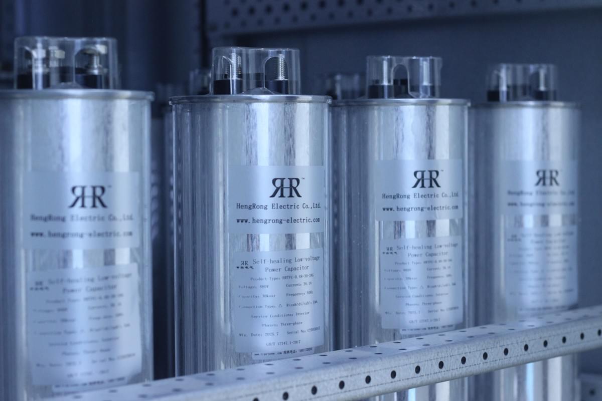
In an ideal state, reactors and capacitors only consume reactive power without consuming active power. When connected to a power source, they participate solely in the exchange of energy without actually consuming any energy. Reactors can be used for reducing AC voltage and limiting current. Inductors and capacitors can form resonant circuits for frequency selection, filters, equalizers, and other networks. In single-phase AC motors, capacitors act as phase shifters to generate torque. In the power grid, capacitors are used to improve the power factor.
Keywords:
Capacitor; Reactor; Voltage Reduction; Power Factor
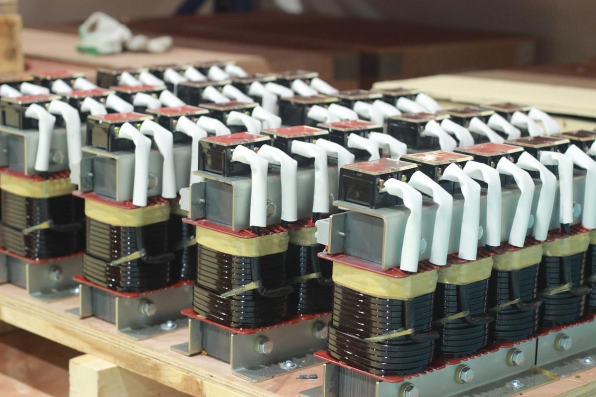
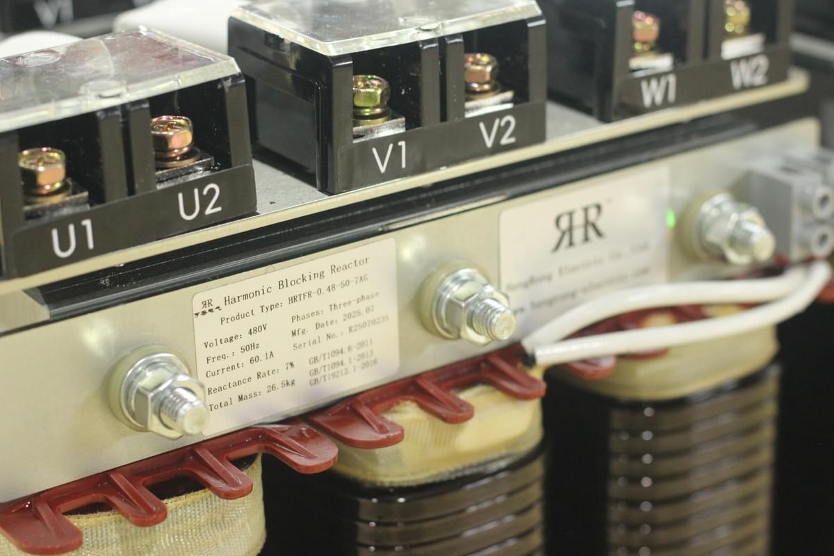
Using series reactors in capacitor compensation circuits can effectively improve the power factor of the power system, suppress inrush currents when capacitor banks are switched, and mitigate high-order harmonics in the grid. They also address harmonic-induced overloads, reduce operational overvoltage during switching, ensure safe capacitor bank operation, optimize voltage waveforms, improve power supply quality, and enhance system stability and safety.
1. Series Capacitor Compensation
Series compensation refers to directly connecting capacitors in series in high-voltage transmission lines to optimize line parameters, prevent excessive voltage drops, improve power transmission capacity, and reduce line losses. This method is mainly applied to long-distance high-voltage transmission lines and is rarely used at the consumer side. The earliest applications were abroad, with China’s first installation at Xuzhou Sanbao Station.

In long transmission lines, inductive reactance dominates over resistance. Series capacitors counteract line inductance, effectively “shortening” the line length, compensating reactive power, and enhancing system stability and safety.
Key functions include:
- Boosting voltage at the receiving end: Reduces voltage drop and typically increases terminal voltage by 10%–20%.
- Enhancing transmission capacity: Series compensation reduces voltage drops and power losses, significantly increasing transmission capacity.
- Optimizing power distribution: Adjusting series capacitor placement changes system reactance to direct current flow and balances load distribution.
- Improving steady-state stability: In case of faults and partial line disconnection, forced adjustment of series capacitor quantity quickly reduces equivalent reactance, increases transfer limit, and ensures stable operation.
For lines shorter than 52.08 km, shunt capacitors are preferable; for longer lines, series compensation is recommended.
2. Shunt Capacitor Compensation
Shunt capacitors installed on system busbars can absorb capacitive reactive power and supply inductive reactive power to the system, improving power factor and bus voltage. This reduces inductive reactive power flow, increases active power transfer, and lowers line losses.

Common methods:
- Centralized compensation: Capacitor banks installed on substation busbars to improve overall power factor and reduce reactive losses on high-voltage lines.
- Distributed compensation: Capacitors installed on distribution busbars (high or low voltage) for localized improvement.
- Local compensation: Capacitors installed near inductive loads (e.g., asynchronous motors) to improve power factor and voltage quality, suitable for smaller equipment.
3. Shunt Reactors
In ultra-high-voltage, long-distance transmission lines, light-load or no-load conditions cause significant charging of reactive power. As voltage increases, charging power increases, leading to voltage rise, power flow issues, and self-excitation risks. Shunt reactors offset line capacitance with inductance, reducing overvoltage.

4. Series Reactors
Functions include:
- Reactive power compensation: Improves power factor while increasing the proportion of active power in the network.
- Reducing design capacity: Raising the power factor (e.g., from 0.8 to 0.95) can significantly reduce required generator and transformer capacity, thus lowering investment costs.
- Reducing line losses: Higher power factor after compensation reduces line losses, improves active power transfer ratio, and enhances system efficiency.

5. Engineering Case Study
In one substation reactive power automatic compensation project, calculations determined a required compensation capacity of 1,800 kV (300 kV + 600 kV + 900 kV) plus 6% reactors to filter 5th and higher-order harmonics.
The main transformer model was S11-20000/110/10.5, rated voltage 10.5 kV, maximum operating voltage 12 kV. Single-phase capacitors rated 12/3 kV were selected.
If using German Hertz capacitors, 9 units were installed (max 400 kV each), totaling 2,400 kV. If using Beijing Yingbo capacitors, 12 units (max 300 kV each) were installed, also totaling 2,400 kV.
6. Conclusion
Both series and parallel connections of capacitors and reactors have distinct roles and advantages. Series connections fundamentally offset reactive power, while parallel connections adjust reactive power through equipment configuration.
________________________________________________________________________________________
Hengrong Electric is committed to the research, development, manufacturing, and sales of capacitors and their supporting equipment, high- and low-voltage complete reactive power compensation devices, as well as various power electronic components and instruments. The company also provides technical services, technical development, technical consulting, and technical exchange for electrical products.
Hengrong Electric Co., Ltd.
www.hengrong-electric.com
