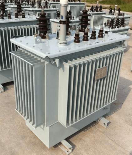
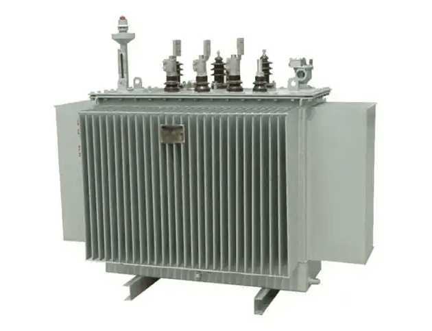
On summer evenings, the hum of air conditioner outdoor units and the constant operation of refrigerators immerse every household in the comfort brought by electricity. Behind this, oil-immersed transformers silently play the role of "power transfer stations". They can step down the high-voltage electricity transmitted by power plants into low-voltage electricity usable by residents. Once a fault occurs, it may cause a power outage in the area at best, or even trigger a fire at worst, directly threatening residential electricity use and power grid safety. Among all types of transformer faults, "winding overheating" is undoubtedly the most hidden "killer". Traditional detection methods either rely on indirect data to "guess faults" or have delayed responses that "miss opportunities". Now, the "Method for Detecting Winding Overheating Faults in Oil-Immersed Transformers Based on Infrared Thermal Imaging" developed by Engineer Liu Yan from the Skill Training Center of State Grid Sichuan Electric Power Company provides a brand-new solution to this industry problem, building an "intelligent protective wall" for power grid safety with technology.
I. The "Hidden Danger" of Transformers: Why Traditional Detection Fails to Tackle Winding Overheating?
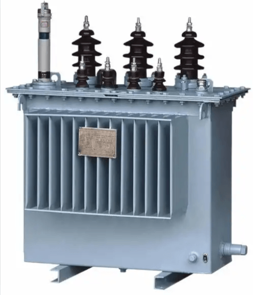
The core of an oil-immersed transformer is its windings—a set of copper coils wrapped around an iron core. Electric current passes through the windings to complete voltage conversion, just like the "power blood vessels" of the human body. However, during long-term operation, factors such as load fluctuations, insulation aging, design defects, and insufficient maintenance can all cause abnormal temperature rise in the windings: slight overheating will accelerate the aging of the insulation layer and shorten the transformer's service life; in severe cases, it will burn the windings and trigger malignant accidents such as oil injection and fire. According to industry statistics, about 30% of transformer faults are caused by winding overheating, which is a key problem that must be solved in power grid operation and maintenance.
Nevertheless, traditional detection methods have always had "inherent shortcomings" and are difficult to accurately capture this "hidden killer":
- Indirect Parameter Inference Method: For example, the detection technology based on improved Support Vector Machine (SVM) needs to collect electrical parameters such as the transformer's current and voltage, and then build a fault model through algorithms. However, these parameters are not directly related to the winding temperature—just like "judging whether someone has a fever by their cough". They are easily affected by power grid fluctuations and equipment interference, resulting in high rates of missed and false detections.
- Dissolved Gas Analysis (DGA) Method: The insulating oil in the transformer serves both heat dissipation and insulation functions. When the windings overheat, the oil decomposes to produce special gases, and faults can be judged by detecting the content of these gases. However, gas accumulation takes time—usually, faults can only be detected hours or even days after they occur. This method not only fails to provide real-time early warning but also makes it difficult to locate the specific overheating position, which is equivalent to "discovering the problem only after the fault has occurred".
"Traditional methods are like 'a blind person groping for an elephant'—either they cannot accurately locate the fault, or they are too slow to miss the opportunity for disposal," Engineer Liu Yan pointed out in her research. Power grid operation and maintenance urgently need a technology that can "directly observe temperature and judge faults in real time"—and the detection method based on infrared thermal imaging emerged precisely to meet this demand.
II. Infrared Thermal Imaging "Breaks the Deadlock": From "Guessing Temperature" to "Directly Observing Temperature"
The principle of infrared thermal imaging technology is not complicated: any object with temperature radiates infrared energy, and the higher the temperature, the stronger the radiation intensity. An infrared thermal imager is like a "temperature camera" that can convert invisible infrared radiation into a color image—low-temperature areas are usually blue-green, while high-temperature areas are orange-red, making the temperature distribution of the transformer windings "clear at a glance".
However, Engineer Liu Yan's research is not simply the use of infrared thermal imagers. Instead, she has built a complete technical system of "image acquisition - preprocessing - fault identification", which accurately solves three core pain points in the application of infrared detection to transformers:
1. Image Preprocessing: "Professional Retouching" for "Temperature Photos"
The original images captured by infrared thermal imagers often suffer from "distortion" due to environmental interference: noise from the equipment itself causes "snowflakes" in the images; the complex surface structure of the transformer (such as radiators and terminal blocks) leads to low temperature contrast; and due to the transformer's large size, a single shot cannot cover the entire device. To address these issues, the team has made the "temperature photos" "clear and complete" through three key technologies:
- Gaussian Filtering for Noise Reduction: This is equivalent to "smoothing" the image. By performing weighted averaging on each pixel and its surrounding pixels using a Gaussian function, environmental noise is suppressed. For example, if a pixel in the original image shows a temperature of 55°C due to interference, while the surrounding pixels all show 48°C, Gaussian filtering will correct the temperature of this pixel to 49°C based on the weight of pixel distance. This not only eliminates noise interference but also retains the real temperature details, making the image smoother.
- Histogram Equalization to Enhance Contrast: To solve the problem of indistinct temperature differences, the gray levels of the image are redistributed to make high-temperature areas more prominent. For instance, areas with temperatures of 50°C and 52°C in the original image have similar colors, making them difficult to distinguish for both human eyes and algorithms. After processing, the 50°C area appears light green and the 52°C area appears orange-yellow, making temperature differences obvious and facilitating quick identification of abnormal areas.
- Image Stitching to Generate Panoramic Images: To solve the problem that a single shot cannot cover the entire transformer, the team adopts a process of "feature point detection - matching - fusion" to stitch multiple high-definition local images into a complete panoramic temperature image of the transformer. Specifically, local images of the transformer's front, side, and top are taken first; the computer automatically identifies unique "feature points" such as shell screws and radiator gaps; then, the positions of each local image are adjusted through an image registration algorithm; and finally, seamless fusion is performed. The resulting panoramic image not only retains the detailed details of local overheating but also presents the overall temperature distribution of the transformer, providing comprehensive data support for subsequent fault detection.
"The preprocessed images are like upgrading from 'blurry surveillance footage' to '4K high-definition images'—temperature details are clearly visible, laying a solid foundation for accurate fault identification," the team verified in experiments that the noise of the processed images is reduced by more than 40% and the temperature contrast is increased by 35%, fully meeting the accuracy requirements for detecting winding overheating faults in transformers.
2. Fault Identification: Three Layers of "Assurance" to Accurately Locate Overheating Areas
With a clear panoramic temperature image, how to accurately judge "where the overheating area is and whether it is a fault"? The team has designed a three-layer identification system of "image segmentation - enhanced residual network analysis - relative temperature difference verification", which progresses step by step to ensure the reliability of detection results:
- Step 1: Image Segmentation to Initially Screen Suspected Areas: First, a normal temperature threshold is set based on the transformer model and industry standards (for example, the maximum normal operating temperature of a certain type of oil-immersed transformer is 60°C). Then, the algorithm automatically scans the panoramic temperature image and marks all areas where the temperature exceeds the threshold as "suspected overheating areas". This can quickly exclude areas with normal temperatures, focus the detection on areas that may have problems, and reduce the workload of subsequent analysis. For example, if an area in the image shows a temperature of 65°C, which exceeds the normal threshold of 60°C, it will be automatically circled as a key analysis object.
- Step 2: Enhanced Residual Network to Accurately Locate Hotspots: A residual network is an artificial intelligence model trained on a large amount of data. After the team trained it using thousands of temperature images of transformers in normal and fault states, it can accurately identify the highest temperature point in the suspected overheating area and eliminate "false overheating" interference (such as abnormal temperatures caused by direct sunlight or equipment reflection). Specifically, the preprocessed temperature image is input into the enhanced residual network; the model scans the image row by row, locates the maximum temperature value (e.g., 72°C) in the suspected area, and marks the specific position of this hotspot. Compared with traditional algorithms, the enhanced residual network has a stronger ability to identify subtle temperature differences—it can distinguish temperature differences of 1-2°C between adjacent pixels, with an accuracy improvement of more than 20%.
- Step 3: Relative Temperature Difference Method to Eliminate False Detections: Considering that factors such as peak power consumption and ambient temperature rise can cause the overall temperature rise of the transformer, simply relying on "temperature exceeding the threshold" may lead to false detections. For this reason, the team introduced the "relative temperature difference method" as an auxiliary verification method: a normal transformer of the same model and operating condition is selected as a reference; its temperature rise at the same detection point is measured (recorded as ΔT_rise); then, the temperature difference between the transformer to be detected and the normal temperature at the same detection point is measured (recorded as ΔT); and the ratio δ between the two is calculated using the formula δ = (ΔT / ΔT_rise) × 100%. When δ exceeds the set fault threshold (e.g., 150%), the transformer to be detected is judged to have a winding overheating fault; if δ is within the normal range, it is a normal temperature rise caused by the environment or operating conditions, avoiding "wrongly accusing a normal device".
Take a practical example: during the summer peak power consumption period, the winding temperature of a transformer to be detected is 8°C higher than the normal temperature (ΔT = 8°C), while the temperature rise of a normal transformer of the same model under the same operating condition is 5°C (ΔT_rise = 5°C). The calculated δ is 160%, which exceeds the fault threshold of 150%, so it is judged as an overheating fault; if the temperature rise of the normal transformer of the same model is also 8°C, then δ = 100%, which is a normal phenomenon and no alarm is needed. This method effectively eliminates the interference of environmental and operating factors, making fault judgment more objective.
III. Experimental Verification: The New Method "Outperforms" Traditional Technologies in 7 Scenarios
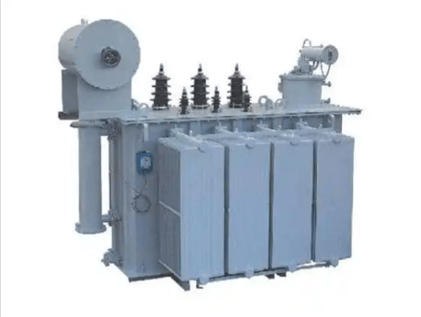
To verify the effectiveness of the detection method based on infrared thermal imaging, Liu Yan's team built a professional experimental platform, using an oil-immersed transformer consistent with practical applications in the power grid (rated voltage: 10 kV, capacity: 1000 kVA, rated current: 31.5 A), equipped with high-precision detection equipment (including a DC resistance tester with a measurement range of 0.1 μΩ ~ 20 kΩ, a thermometer with an accuracy of ±0.5°C, and a DC high-voltage generator with an output of 0 ~ 100 kV). They simulated 7 common overheating scenarios of transformer windings and compared the new method with two traditional detection methods (the method based on improved SVM and the transformer fault diagnosis method based on QPSO-SVM and DGA pentagonal interpretation tool).
The Kappa value was used as the evaluation index for detection accuracy in the experiment. The Kappa value is calculated by considering the consistency probability between the detection results and the actual fault situation, and then excluding the impact of random guessing. A higher value indicates more accurate detection (with a full score of 1). The comparison results show that the Kappa value of the new method is significantly higher than that of traditional methods in all scenarios:
- In the scenario of local winding overheating, the Kappa value of the new method reaches 0.85, while that of Comparative Method 1 is 0.76 and Comparative Method 2 is 0.79. The new method can more accurately capture small-scale local hotspots.
- In the scenario of overall winding overheating, the Kappa value of the new method is 0.81, which is higher than that of Comparative Method 1 (0.71) and Comparative Method 2 (0.74), avoiding false detections caused by the interference of indirect parameters in traditional methods.
- In the scenario of poor contact between windings and the iron core (where temperature differences are subtle), the Kappa value of the new method is 0.69, still higher than that of Comparative Method 1 (0.65) and Comparative Method 2 (0.61), demonstrating its sensitive ability to identify subtle temperature changes.
- In the scenario of winding overheating caused by cooling system faults, the Kappa value of the new method is 0.68, while that of Comparative Method 1 and 2 is 0.61 and 0.64 respectively. The new method can capture the "slow temperature rise" fault trend in real time, avoiding the lag of traditional methods that rely on gas detection.
- The new method performs most prominently in the scenario of transient winding overheating caused by sudden load increase, with a Kappa value as high as 0.86, far exceeding that of Comparative Method 1 (0.78) and Comparative Method 2 (0.81). This is because the new method can complete temperature shooting and analysis within a few seconds, capturing the transient fault that "comes and goes quickly".
- In the scenario of long-term winding overheating caused by insulation aging, the Kappa value of the new method is 0.74, while that of Comparative Method 1 is 0.67 and Comparative Method 2 is 0.70. The new method can capture the subtle temperature rise of 1-2°C in the early stage, buying time for preventive maintenance.
- In the scenario of winding overheating caused by external short circuits, the Kappa value of the new method is 0.72, compared with 0.60 for Comparative Method 1 and 0.63 for Comparative Method 2. The new method is not affected by current fluctuations caused by short circuits and directly uses temperature as the judgment basis, resulting in more stable accuracy.
It can be seen from the experimental results that the new method not only performs well in "simple faults" (such as local and overall overheating) but also demonstrates advantages that traditional methods cannot match in "complex faults" (such as poor contact and cooling system faults) and "special faults" (such as transient overheating and early aging), fully meeting the power grid operation and maintenance requirements for "accuracy, real-time performance, and reliability" in fault detection.
IV. Practical Value: Bringing "Three Transformations" to Power Grid Operation and Maintenance
This detection method based on infrared thermal imaging not only performs well in the laboratory but also brings a "qualitative leap" to practical power grid operation and maintenance, solving three long-standing pain points of traditional methods:
1. From "Indirect Inference" to "Direct Observation": Significantly Improving Detection Accuracy
Traditional methods rely on indirect indicators such as electrical parameters and gas content, which is like "scratching the surface through clothing" and makes it difficult to accurately locate faults. The new method directly observes the temperature distribution of the windings, making the overheating position and temperature value "clear at a glance". In the pilot application at a substation in Sichuan, the new method successfully detected a "hidden overheating fault" in a transformer—the overheating point was located inside the windings, blocked by the iron core, and no abnormality was found by traditional DGA detection. However, the infrared thermal imaging panoramic image clearly showed that the temperature of this area reached 68°C. Operation and maintenance personnel promptly disassembled and overhauled the transformer, avoiding a power outage accident caused by fault expansion.
2. From "Delayed Response" to "Real-Time Early Warning": More Timely Fault Disposal
Traditional DGA detection requires waiting for gas accumulation in the oil, often "alerting only after the fault has occurred". The new method can realize 24-hour real-time monitoring, and an alarm is triggered immediately when the temperature is abnormal. During the summer peak power consumption period in 2024, the load of a transformer in a certain area of Sichuan suddenly increased due to residents concentratedly turning on air conditioners. The new method captured the transient temperature rise of the windings within 3 seconds. Operation and maintenance personnel reduced the load of this transformer through remote control, successfully avoiding a power outage for more than 2,000 households in the area and ensuring the stability of residential electricity use.
3. From "Close-Range Operation" to "Non-Contact Detection": More Secure Operation and Maintenance
Transformers carry high voltage during operation. Traditional detection requires operation and maintenance personnel to wear insulating equipment and operate at close range, which poses a risk of electric shock. The new method uses an infrared thermal imager to complete temperature shooting from 5 to 10 meters away, without the need to contact high-voltage equipment, greatly reducing the safety risks for operation and maintenance personnel. "In the past, detecting a transformer required multiple insulation protections in advance, which was time-consuming and labor-intensive; now we can complete the detection while standing in a safe area, which improves both efficiency and safety," commented the operation and maintenance personnel who participated in the pilot application.
V. Future Outlook: Making the "Sharp Eyes" More Intelligent and Accurate
Engineer Liu Yan's team has not stopped at the existing achievements. In the research, they have clearly defined two future directions for deepening the technology to further improve its practicality and intelligence:
- Optimizing Infrared Measurement Accuracy to Resist Environmental Interference: Current infrared detection is easily affected by environmental factors such as rain, snow, fog, and direct sunlight, leading to errors in temperature measurement. Next, the team plans to develop an "anti-interference infrared lens" and combine it with an environmental parameter compensation algorithm to correct the impact of weather and light on measurement results, reducing the temperature measurement error from the current ±1°C to ±0.5°C, so that the technology can work stably under complex climate conditions.
- Integrating In-Depth AI Analysis to Realize "Diagnosis + Disposal" Integration: The current enhanced residual network can already accurately locate hotspots. In the future, the AI model will be further upgraded to add the function of "fault cause identification"—by analyzing the characteristics of temperature distribution (such as hotspot shape and temperature rise rate), it can automatically judge whether overheating is caused by insulation aging, sudden load increase, or cooling system failure, and generate targeted disposal suggestions (such as "it is recommended to replace the insulation layer" or "the load needs to be reduced"). This will greatly reduce the reliance of operation and maintenance personnel on experience, realize the integration of "automatic fault diagnosis + disposal plan recommendation", and further improve the efficiency of power grid operation and maintenance.
Conclusion: Technology Guards the Power Grid and Lights Up Every Household
The detection of winding overheating faults in oil-immersed transformers seems to be a "professional problem" in the power industry, but it is actually closely related to everyone's daily life—it affects whether we can use air conditioners stably in summer, whether we can enjoy heating with peace of mind in winter, whether enterprise production can operate continuously, and whether urban operation can maintain normalcy. The detection method based on infrared thermal imaging developed by Engineer Liu Yan breaks the limitations of traditional technologies with science and technology, enabling transformer fault detection to move from "a blind person groping for an elephant" to "seeing clearly every detail".
The practical application of this technology can not only reduce the number of power outages caused by transformer faults and lower the cost of power grid operation and maintenance but also provide a "solid guarantee" for the safe and stable operation of the power system. When we turn on the lights late at night and enjoy the coolness in the heat, it is precisely such "power technologies" that are silently guarding us. In the future, with the continuous optimization and upgrading of technology, it is believed that more innovative achievements like this will emerge, making the power grid more intelligent and reliable, and continuously lighting up every household.
Hengrong Electric Co., Ltd.
We specialize in providing high-efficiency reactive power compensation and power quality optimization solutions. With over 20 years of industry experience, our products excel in enhancing grid efficiency, reducing energy consumption, and ensuring system stability.
Our core products and services include:
Low-voltage Reactive Power Compensation and Power Quality Optimization:
Self-healing Capacitors:
Improve power factor, optimize grid power quality, and extend equipment lifespan with self-healing functionality.
Increased Safety Capacitors:
Designed for hazardous environments with combustible gases, providing high safety and explosion-proof features.
Tuned Reactors:
Effectively absorb grid harmonics, improve voltage waveform stability, and protect capacitors.
Composite and Thyristor Switches: Reliable capacitor switching devices with no inrush current, low noise, and stable operation.
High-voltage Reactive Power Compensation Solutions:
High-voltage Capacitors and Reactors: Enhance high-voltage grid stability, effectively compensate reactive power, and suppress harmonics.
Power Quality Governance:
Active Power Filters (APF):
Eliminate harmonics, improve power quality, and ensure system stability.
Static VAR Generators (SVG):
Provide dynamic reactive power compensation with fast and smooth system response.
Smart and Customized Solutions:
Offer smart power quality management controllers and intelligent compensation devices that adapt to complex grid environments, ensuring optimal operation.
Why Choose Hengrong Electric?
Industry Experience: We have extensive experience in power quality optimization, having delivered reliable solutions for numerous clients across various industries.
Customized Services: We provide tailored solutions based on specific client needs, ensuring the maximum benefits for every project.
Technical Assurance: Our products are internationally certified and feature advanced technology, ensuring high efficiency, reliability, and long-term stability.
