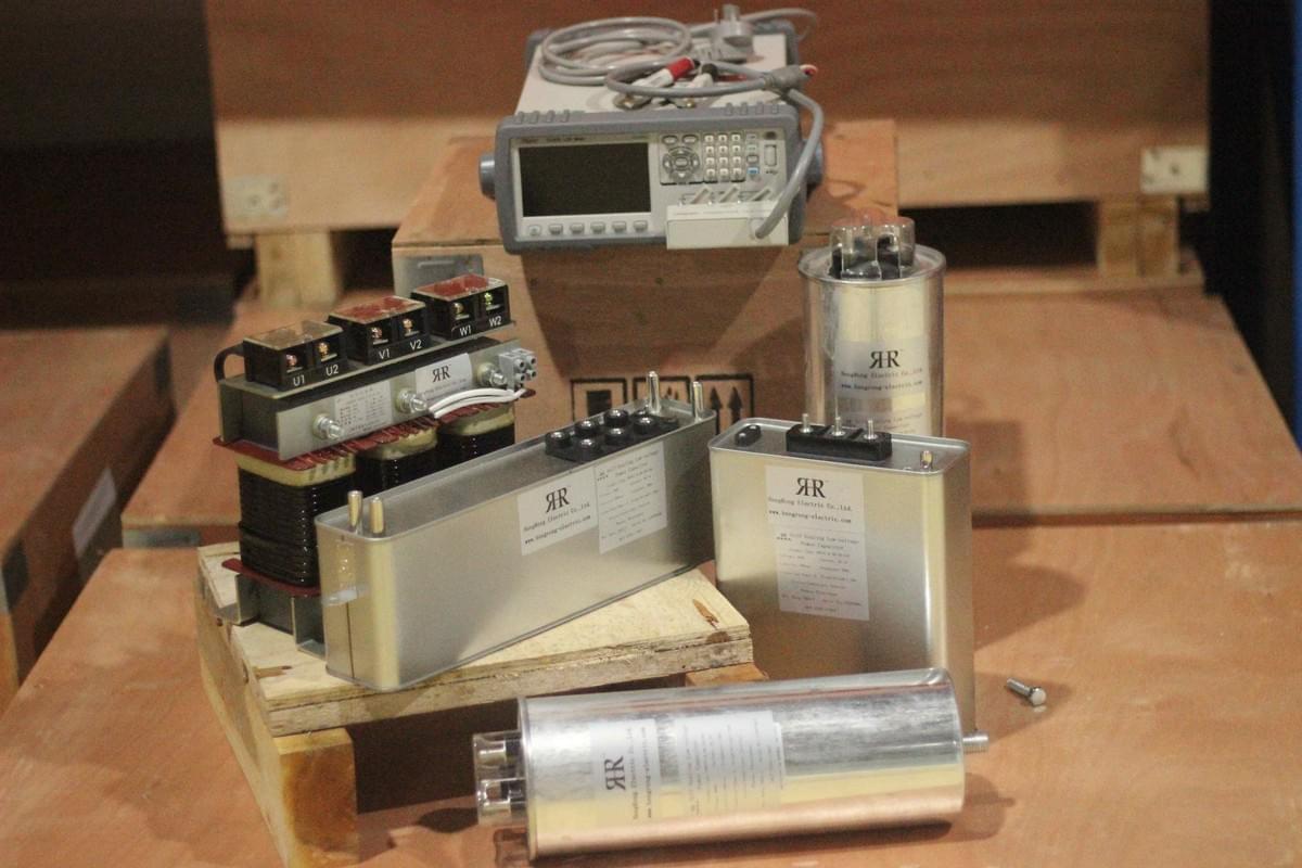
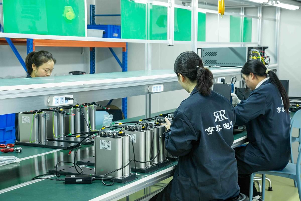
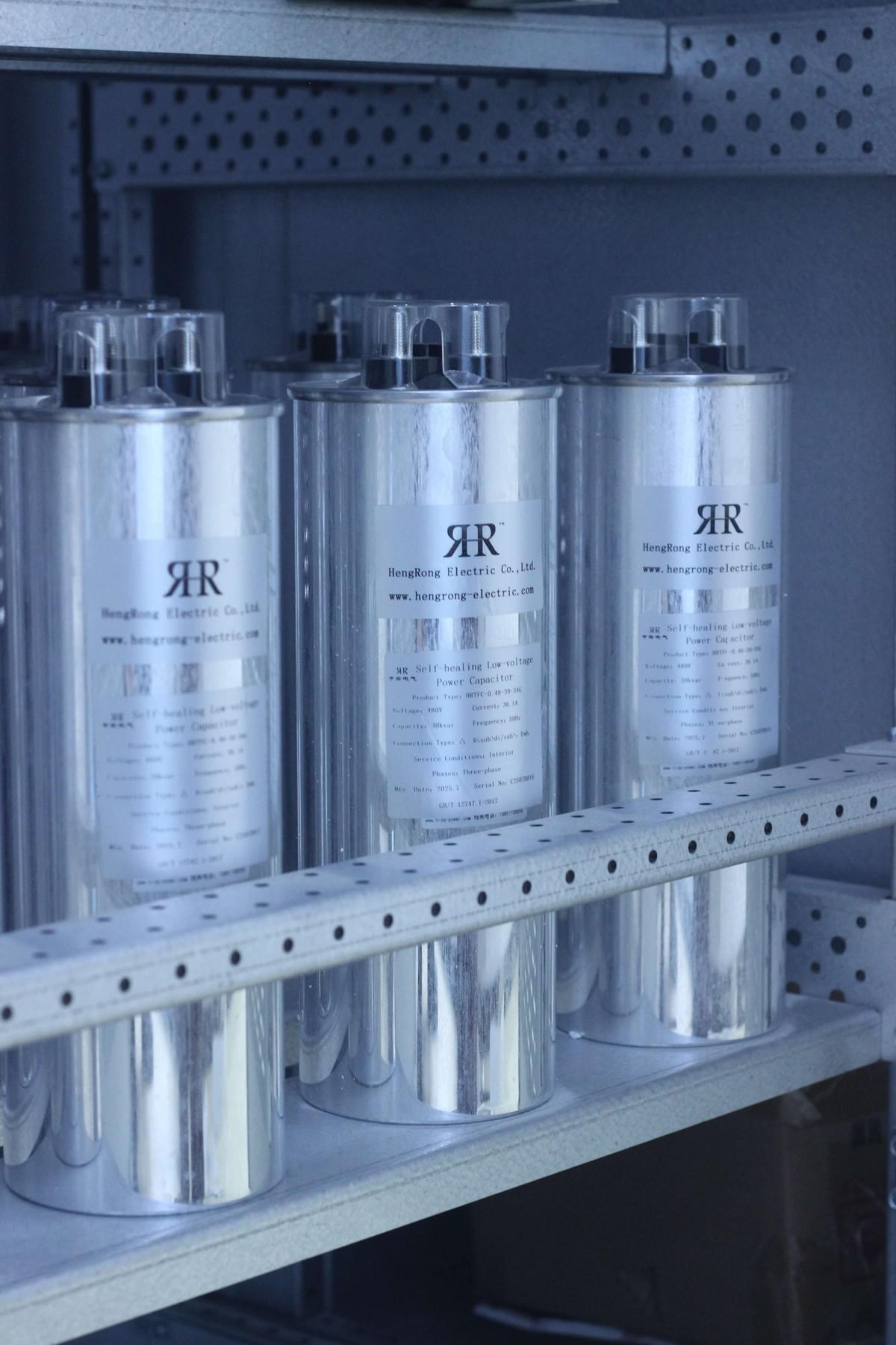
In industrial production and civil power supply scenarios, reactive power generated by equipment resistance during power transmission often leads to increased power loss, significant voltage fluctuations, and low utilization of power transformation and distribution equipment. As the core component of reactive power compensation, low-voltage capacitors have become the key to solving these problems due to their advantages of flexible adaptation and controllable costs. This article explains in detail how to achieve improved power supply efficiency and maximized economic benefits through the scientific application of low-voltage capacitors, covering the functions, compensation methods, technical key points, and capacity calculation of low-voltage capacitor reactive power compensation, providing practical references for enterprises and power systems.

I. Core Value of Low-Voltage Capacitor Reactive Power Compensation: Four Functions to Solve Power Supply Challenges
By compensating for reactive power in power transmission, low-voltage capacitors significantly improve the power supply system in four dimensions: equipment utilization, energy consumption, voltage stability, and grid power factor, making them a "cost-effective choice" for power optimization.
1. Improve Utilization of Power Transformation and Distribution Equipment, Reduce Investment Costs
Low power factor loads occupy a large amount of capacity of power transformation and distribution equipment (such as transformers and distribution cabinets), resulting in "overload operation" or "capacity waste" of the equipment. Parallel connection of low-voltage capacitors for reactive power compensation can reduce the required capacity of the equipment, thereby directly lowering investment, operation, and maintenance costs.
- Core Formula: The reduced capacity (ΔS) of power transformation and distribution equipment can be calculated using the formula:
ΔS = P/COSφ₁ - P/COSφ₂ = P×(COSφ₂ - COSφ₁)/(COSφ₂×COSφ₁)
(Where P is the load active power, COSφ₁ is the power factor before compensation, and COSφ₂ is the power factor after compensation)
- Example Effect: Taking a 1000kW load as an example, the power factor increases from 0.7 (before compensation) to 0.95 (after compensation). According to the formula, the equipment capacity can be reduced by 376kVA. For new projects, this means that smaller-capacity transformers and distribution cabinets can be selected, reducing equipment procurement costs. For existing projects, it can lower basic electricity fee expenses (in some regions, electricity fees are charged based on equipment capacity), saving over 10,000 RMB annually.
2. Reduce Power Transmission Loss, Improve Energy Utilization
During long-distance power transmission, reactive current increases line loss (loss is proportional to the square of current). Low-voltage capacitors reduce the total current in the line by compensating for reactive power, fundamentally reducing losses.
- Application Scenario: The energy-saving effect of low-voltage capacitors is particularly significant in long-distance power supply scenarios such as industrial parks and rural irrigation. For example, a 10kV line supplies power to a factory 2km away. Before compensation, the line loss rate is 8%; after installing low-voltage capacitors, the loss rate drops to below 5%. Based on an annual power supply of 1 million kWh, the approximate annual power saving is 30,000 kWh, equivalent to over 20,000 RMB in electricity fee savings.
3. Stabilize Voltage, Ensure Normal Operation of Equipment
During peak power consumption periods, insufficient reactive power easily leads to terminal voltage drop (e.g., workshop motors fail to start due to low voltage, and civil household appliances shut down frequently). Low-voltage capacitors can supplement reactive power in real time, adjust the amplitude of voltage fluctuations, and control the voltage within the range allowed by national standards (220V±7%).
- Practical Case: During the summer peak power consumption period of a food processing plant, the workshop voltage often dropped to 190V, causing the freezing equipment to shut down. After installing two sets of 100kvar low-voltage capacitors, the voltage stabilized at 210-220V, the equipment failure rate decreased by 40%, and production continuity was significantly improved.
4. Optimize Grid Power Factor, Avoid Electricity Fee Fines
China's Power Supply Business Rules clearly stipulate that the power factor of industrial users must reach 0.9 or above; otherwise, reactive power surcharge fines will be imposed (e.g., a 5% fine of the total electricity fee when the power factor is 0.7). Low-voltage capacitors can accurately increase the power factor to the compliance range, even exceeding the standard (e.g., above 0.95), helping enterprises avoid fines. In some regions, enterprises can even enjoy electricity fee reduction incentives.

II. Two Core Methods of Low-Voltage Capacitor Reactive Power Compensation: Select Adaptive Solutions on Demand
According to the power supply range and load distribution characteristics, low-voltage capacitor reactive power compensation is mainly divided into two methods: "centralized compensation" and "on-site compensation". Enterprises need to select based on their own scenarios to maximize the compensation effect.
1. Centralized Compensation: Suitable for Large-Scale, Multi-Load Scenarios
- Installation Method: Configure multiple sets of low-voltage capacitors (usually cabinet-type capacitor banks with a single set capacity of 50-300kvar) on the distribution bus of the low-voltage distribution station to centrally compensate for reactive power within the entire power supply range;
- Core Advantages: Convenient management, automatic switching can be realized through a unified controller (such as PLC), adapting to scenarios where multiple loads operate simultaneously (e.g., industrial parks, large shopping malls);
- Applicable Scenarios: Areas with relatively concentrated loads and short lines (≤500 meters). For example, an industrial park distribution station installed 4 sets of 200kvar low-voltage capacitors, which can cover the reactive power compensation needs of 10 small and medium-sized factories, and the overall power factor increased to above 0.92.
2. On-Site Compensation: Suitable for Single Large Load, Long-Distance Scenarios
- Installation Method: Install low-voltage capacitors directly near electrical equipment (e.g., beside motors, inside pump station control cabinets), connect them in parallel with the load for power supply, and compensate for the reactive power generated by the equipment on-site;
- Core Advantages: Avoids the transmission of reactive current in the line, reduces local line loss, and is especially suitable for long-distance power supply or single high-power equipment (e.g., motors above 10kW, rural irrigation pumps);
- Applicable Scenarios: Rural irrigation stations (line length 1-3km), large workshop motors (e.g., 50kW compressors). For example, after installing a 50kvar low-voltage capacitor for a rural irrigation pump, the line loss decreased by 35%, the irrigation efficiency increased by 20%, and there was no need to wait for off-peak power consumption to start the equipment.
III. Technical Key Points of Low-Voltage Capacitor Reactive Power Compensation: Avoid Risks, Ensure Stable Operation
In the application of low-voltage capacitors, three key issues—"inrush current prevention, harmonic amplification prevention, and self-excitation prevention"—must be focused on to avoid equipment damage or system failures and ensure the safe and reliable operation of the compensation system.
1. Inrush Current Prevention: Avoid Current Impact When Capacitors Are Put into Operation
When low-voltage capacitors are connected to the power grid, an inrush current with a peak value 5-10 times the rated current is likely to occur instantly, which may break down the capacitor insulation layer or burn the contactor.
- Solutions:
- Select low-voltage capacitors with current-limiting resistors, or connect current-limiting reactors in series in the input circuit to reduce the peak value of inrush current;
- Adopt delayed switching technology to avoid simultaneous switching of multiple capacitor sets (interval time ≥30 seconds);
- Inrush Current Calculation Reference: The inrush current (Is) can be obtained through an approximate calculation using the formula: Is = In×√(S/Q) (Where In is the rated current of the capacitor, S is the short-circuit power at the installation location, and Q is the capacitor capacity). During design, it is necessary to ensure that the peak value of inrush current ≤5 times the rated current.
2. Harmonic Amplification Prevention: Avoid LC Circuit Resonance
Low-voltage capacitors and line inductors form an LC circuit. If there are 3rd, 5th, 7th, or other harmonics in the power grid, resonance is likely to occur, leading to harmonic amplification, capacitor overheating, and abnormal voltage rise.
- Solutions:
- Connect reactors with a certain reactance value (usually 6% or 7% reactance) in series in the low-voltage capacitor circuit to change the resonance frequency of the LC circuit and avoid harmonic frequencies;
- Install harmonic detectors to monitor the harmonic content of the power grid in real time. If the harmonics exceed the standard (e.g., total harmonic distortion rate >5%), it is necessary to use active power filters in combination.
3. Self-Excitation Prevention: Control Capacitor Capacity
If the capacity of low-voltage capacitors is too large, it will cause the motor to generate self-excitation voltage when it stops, leading the motor to enter a power generation state and damaging the equipment insulation.
- Solutions:
- The compensation capacity must be smaller than the motor's no-load capacity, usually taking 0.9 times the motor's no-load capacity. The calculation formula is: Qc = 0.9×3UI₀ (Where U is the system voltage, and I₀ is the motor no-load current);
- For example, a 10kW motor has a no-load current of 5A and a system voltage of 380V. According to the formula, the capacity of the low-voltage capacitor that can be selected is 0.9×3×380×5≈5130var (i.e., approximately 5kvar), avoiding self-excitation caused by excessive capacity.

IV. Capacity Calculation and Control Selection of Low-Voltage Capacitor Reactive Power Compensation: Accurately Match Requirements
Scientifically determining the capacity of low-voltage capacitors and selecting an appropriate switching control method are the keys to ensuring the compensation effect. Strict calculations based on load parameters are required to avoid "over-compensation" or "under-compensation".
1. Compensation Capacity Calculation: Accurate Calculation Based on Power Factor Target
- Core Formula: The required low-voltage capacitor capacity (Qc) is calculated based on the change in power factor: Qc = P×(tgφ₁ - tgφ₂) (Where P is the load active power, tgφ₁ is the tangent value corresponding to the power factor before compensation, and tgφ₂ is the tangent value corresponding to the target power factor after compensation);
- Calculation Example: The active power of a workshop load is P=800kW, the power factor before compensation is COSφ₁=0.7 (tgφ₁≈1.02), and the target power factor after compensation is COSφ₂=0.95 (tgφ₂≈0.33). Then Qc=800×(1.02-0.33)=552kvar. In practice, 6 sets of 100kvar low-voltage capacitors (total capacity 600kvar) can be selected, with a small amount of margin reserved to cope with load fluctuations.
2. Switching Control Method: Select Based on Load Stability
- Manual Switching: Suitable for scenarios with stable loads and low usage frequency (e.g., small workshop motors). Low-voltage capacitors are switched manually through operation switches, with low cost;
- Automatic Switching: Suitable for scenarios with large load fluctuations and continuous operation (e.g., shopping malls, chemical plants). PLC or dedicated controllers are used to automatically switch capacitor sets based on the power factor (e.g., switch on when the power factor is below 0.9, switch off when it is above 0.95) to avoid over-compensation;
- Delayed Switching: Regardless of manual or automatic switching, a delay (≥30 seconds) must be set to prevent inrush current impact caused by frequent switching of capacitors and extend the service life of the equipment.
V. Conclusion: Low-Voltage Capacitor Reactive Power Compensation — The Preferred Solution for Enterprise Cost Reduction and Efficiency Improvement
Against the backdrop of growing power demand and increasing energy-saving requirements, low-voltage capacitor reactive power compensation has become the core means for enterprises to optimize their power systems, with the triple advantages of "improving efficiency, reducing losses, and saving costs". Whether in industrial production, commercial operations, or agricultural irrigation, the value of low-voltage capacitors can be fully exerted by scientifically selecting compensation methods, accurately calculating capacity, and avoiding technical risks, achieving the dual goals of stable operation of the power supply system and improved economic benefits.

If your enterprise is facing problems such as substandard power factor, high electricity fees, or difficulty in starting equipment, please leave a message to inform us of the load type (e.g., motor power, power supply line length), current power factor, and other parameters. Hengrong Electric Co.,Ltd will provide you with a customized low-voltage capacitor reactive power compensation solution to help your enterprise reduce costs and improve efficiency!
