
Low-Voltage Reactive Power Compensation: The Key to Enhancing Power System Efficiency
Low-Voltage Reactive Power Compensation: The Key to Enhancing Power System Efficiency
With the rapid development of modern industry and the continuous growth of residential electricity demand, the complexity of power systems is increasing day by day. In low-voltage distribution networks, the widespread application of inductive loads such as motors, transformers, and air conditioners generates large amounts of reactive power, which not only reduces the power factor of power systems but also increases line losses and voltage fluctuations. As a core means to improve power quality and enhance system efficiency, low-voltage reactive power compensation technology effectively balances reactive power supply and demand, reduces electrical energy loss, and ensures the safe and stable operation of equipment through the scientific configuration of compensation devices. This article starts from the basic concepts of reactive power compensation, systematically expounds on the types of compensation devices, their working principles, selection strategies, and practical application effects, providing comprehensive references for power system optimization.

I. Core Concepts and Importance of Reactive Power Compensation
1.1 What is Reactive Power Compensation?
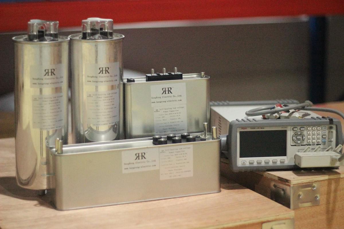
In AC power systems, the transmission and conversion of electrical energy require two types of power support: active power (P) and reactive power (Q). Active power is the energy directly used for performing work, such as driving motors and powering heating equipment, while reactive power is the energy that maintains the alternating conversion of electric and magnetic fields, primarily used by inductive loads to establish magnetic fields and ensure proper equipment operation. Reactive power compensation technology provides the required reactive power to inductive loads by connecting reactive power sources such as capacitors, reducing the reactive power transmitted through the grid, and thereby achieving system power balance.
1.2 Core Roles of Reactive Power Compensation
- Improving Power Factor: The power factor, the ratio of active power to apparent power, directly reflects power system efficiency. Uncompensated inductive loads typically result in a low power factor (usually below 0.7). Reactive power compensation can increase the power factor to above 0.9, reducing the grid's reactive power transmission burden.
- Reducing Line Losses: According to Joule-Lenz's law, line losses are proportional to the square of the current. Reactive power compensation reduces reactive current in lines, which can lower line losses by 30%~50% and significantly save electrical energy.
- Improving Voltage Quality: Insufficient reactive power causes voltage drops at line endpoints, affecting equipment operation. Compensation devices stabilize voltage levels, preventing issues such as motor burnout and equipment malfunctions caused by voltage fluctuations.
- Increasing Equipment Capacity: The capacity of transformers, cables, and other equipment is limited by apparent power. Reactive power compensation reduces the capacity occupied by reactive power, potentially increasing the effective active power output of equipment by 10%~20%.
II. Main Types and Working Principles of Low-Voltage Reactive Power Compensation Devices
2.1 Balanced Reactive Power Compensation Devices
Balanced reactive power compensation devices are the most widely used traditional compensation equipment in low-voltage distribution networks, suitable for scenarios with relatively balanced three-phase loads, such as agricultural irrigation systems and small industrial workshops.
2.1.1 Structure and Working Principle
The device comprises a controller, a capacitor bank, a switching mechanism (contactor or thyristor), and protection components. The controller calculates the system's current power factor and reactive power demand by real-time monitoring of three-phase voltages and one-phase current. When the power factor falls below the set threshold, it automatically switches on the corresponding capacity of the capacitor bank; when the power factor exceeds the cut-off threshold, it disconnects the capacitor bank to achieve dynamic compensation.
2.1.2 Switching Conditions and Control Logic
- Switch-on condition: Power factor < 0.9 (configurable), and line current > light-load threshold (usually 20% of rated current);
- Switch-off condition: Power factor > 0.95 (configurable), or line voltage > 1.1 times rated voltage;
- Protection logic: Upon detecting overvoltage, overcurrent, or excessive harmonics, the capacitor bank is immediately switched off to prevent equipment damage.
2.1.3 Limitation Analysis
Balanced compensation devices assume symmetrical three-phase loads and only provide overall compensation for three-phase reactive power. In actual grids, residential and commercial loads often exhibit three-phase imbalance. In such cases, the device may experience over-compensation in one phase and under-compensation in another, reducing compensation effectiveness or even causing resonance.
2.2 Phase-Separated Graded Reactive Power Compensation Devices
To address three-phase imbalance, phase-separated graded reactive power compensation devices achieve independent phase compensation through refined control technology, suitable for complex load scenarios such as urban distribution networks and high-rise buildings.
2.2.1 Technical Characteristics and Advantages
The device adopts a three-phase independent detection and switching design. The controller monitors three-phase voltages, currents, and reactive power of each phase in real-time, providing precise reactive power compensation for each phase through graded single-phase capacitor banks. Compared with balanced compensation, its core advantages include:
- Resolving compensation deviations caused by three-phase load imbalance;
- Avoiding over-compensation under light load conditions;
Incorporating harmonic suppression functionality to adapt to nonlinear load environments.
2.2.2 Switching Strategy and Protection Mechanism
- Phase-separated switching: Independently controls the switched-on capacity of capacitors in phases A, B, and C based on reactive power calculations for each phase;
- Dynamic response: Uses thyristor switching mechanisms to achieve millisecond-level response speeds, adapting to rapid load changes;
- Harmonic protection: Features a built-in harmonic detection module that automatically switches off capacitors when voltage total harmonic distortion (THD) exceeds 5%.

III. Selection Principles and Configuration Methods of Reactive Power Compensation Devices
3.1 Core Basis for Selection
3.1.1 Load Characteristic Analysis
- Load type: Pure resistive loads (e.g., lighting) require minimal compensation, while inductive loads (e.g., motors) need prioritized compensation;
- Load volatility: Stable loads (e.g., production lines) can use static compensation, while fluctuating loads (e.g., elevators) require dynamic compensation;
- Three-phase balance: Scenarios with imbalance exceeding 10% must use phase-separated compensation devices.
3.1.2 System Parameter Calculation
- Reactive power deficit calculation: Based on total load capacity and current power factor, calculate required compensation capacity using the formula Q=P×(tanφ₁-tanφ₂) (where P is active power, φ₁ is the pre-compensation power factor angle, and φ₂ is the target power factor angle);
- Harmonic content detection: Measure harmonic spectra using power quality analyzers. Scenarios with significant 5th and 7th harmonics require filter reactors;
- Installation environment: High-temperature and humid environments require devices with IP44 or higher protection ratings.
3.2 Selection Schemes for Different Scenarios

3.3 Installation and Commissioning Notes
- Capacitor banks should be installed near load centers to minimize compensation line length;
- Adopt group switching with each group's capacity not exceeding 20% of total capacity to avoid switching impacts;
- During commissioning, measure power factor curves and optimize switching thresholds to prevent frequent cycling.
IV. Common Problems and Solutions of Reactive Power Compensation Devices
4.1 Analysis of Poor Compensation Effect Causes
4.1.1 Over-Compensation and Under-Compensation
Over-compensation manifests as a power factor > 1.0, introducing capacitive current in lines and increasing voltage rise risks; under-compensation means the power factor fails to reach target values, leaving significant losses unaddressed. Core causes include: incorrect compensation capacity calculations, load fluctuations exceeding device response ranges, and uncorrected three-phase imbalance.
4.1.2 Frequent Device Switching
When loads alternate between light and heavy conditions, compensation devices may cycle frequently near switching thresholds, shortening contactor life and impacting the grid. Solutions include: increasing switching hysteresis (e.g., setting a 0.9~0.95 threshold range), using graded compensation to reduce single switching capacity, and selecting thyristor non-contact switches.
4.2 Harmonic Interference and Protection Measures
Harmonics generated by power electronic equipment (e.g., frequency converters, rectifiers) can cause capacitor overheating and protection malfunctions. Protection measures include:
- Series reactors: Suppress 5th and higher harmonics with 4.5%~6% reactance rates;
- Active power filters: Dynamically absorb harmonic currents, controlling total harmonic distortion below 5%;
- Regular detection: Conduct quarterly harmonic spectrum analyses and adjust filtering parameters timely.
4.3 Maintenance and Management Points
- Daily inspections: Check capacitors for bulging and oil leakage, and contactor contacts for burning;
- Regular testing: Annually measure capacitance values and insulation resistance to ensure capacity attenuation does not exceed 10%;
- Data monitoring: Record power factor, compensation capacity, and other data via intelligent controllers to analyze compensation effects and optimize strategies.
V. Practical Application Effects and Future Development of Reactive Power Compensation
5.1 Typical Application Cases
A residential community's original low-voltage distribution system suffered from long-term power factors below 0.8 due to three-phase load imbalance, with 12% line loss rates and frequent voltage drops during summer peaks. After retrofitting with phase-separated graded compensation devices (3 groups of 20kvar capacitors per phase), dynamic compensation increased the power factor to above 0.95, reduced line loss rates to 7%, saved approximately ¥80,000 in annual electricity costs, and significantly improved voltage stability.
A small machinery factory installed balanced compensation devices, increasing power factors from 0.72 to 0.93, reducing transformer output current by 15%, minimizing motor heating, extending equipment service life by approximately 2 years, and achieving an investment payback period of only 8 months.
5.2 Technical Development Trends
- Intelligence: Integrate IoT technology for remote monitoring and automatic diagnosis, using AI algorithms to predict load changes and adjust compensation strategies proactively;
- Modularization: Adopt standardized compensation modules to support flexible expansion and adapt to load growth;
- Integration: Combine reactive power compensation with harmonic management and three-phase balancing functions to enhance comprehensive system performance.
VI. Conclusion
Low-voltage reactive power compensation technology is key to energy conservation, consumption reduction, quality improvement, and efficiency enhancement in power systems. Its application directly impacts grid operational economy and reliability. Through scientific selection, reasonable configuration, and refined management, reactive power compensation devices effectively address issues such as low power factors, excessive line losses, and voltage instability, providing high-quality power support for industrial production and residential life. With smart grid development, reactive power compensation will evolve toward greater precision, efficiency, and intelligence, becoming a core supporting technology for future power system optimization. In practical applications, personalized schemes based on specific load characteristics are essential to fully exploit reactive power compensation's energy-saving potential and promote green, efficient, and sustainable power system development.
Hengrong Electric CO., LTD. offers low-voltage reactive power compensation cabinets, high-voltage reactive power compensation cabinets, and centralized reactive power compensation cabinets, etc.. Welcome to leave a message or call. We are always here to help you.