Hengrong Electrical Co., Ltd.
  • Home
  • Product
  • Agency Recruitment
  • Services
  • Factory & Certification
  • Blog
  • About Us
  • Contact Us
  • …  
    • Home
    • Product
    • Agency Recruitment
    • Services
    • Factory & Certification
    • Blog
    • About Us
    • Contact Us
Request Quote

Reactive Power Compensation and Capacitors: Core Elements for Ensuring Grid Stability and Fault Response Strategies

Self-healing Low-voltage Power Capacitor

In the operation of power systems, reactive power compensation and capacitors have always played a crucial role. With the continuous growth in society's demand for electricity, the quality of the power grid supply has a direct impact on the economy and the safety of electrical equipment. Reactive power compensation, which adjusts the power factor through the use of capacitors, has become a core means of optimizing grid performance. However, capacitors are prone to faults due to various factors during long-term operation. If not resolved promptly, these faults will seriously threaten grid stability. This article will deeply analyze the necessity of reactive power compensation, examine common capacitor faults, and provide targeted preventive measures to help enterprises improve the reliability of their power systems.

I. The Necessity of Reactive Power Compensation: Why Capacitors Are "Indispensable" for Power Grids
Self-healing Low-voltage Power Capacitor

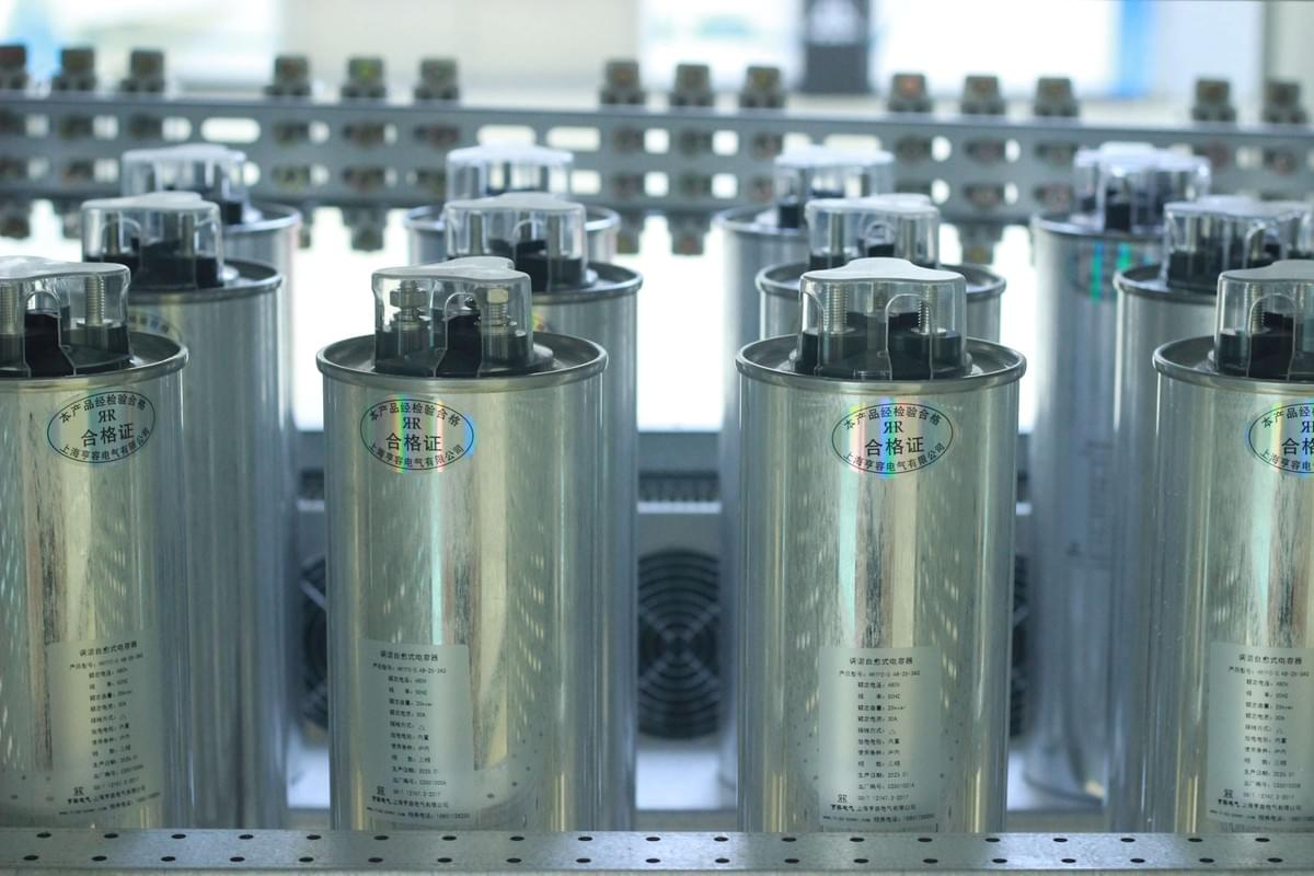
The core function of reactive power compensation is to compensate for reactive power through capacitors and improve the grid power factor, which is crucial for the efficient operation of the power grid. When the power factor is too low, it will bring multiple negative impacts to the power supply equipment. As the core component of reactive power compensation, the stable operation of capacitors directly determines the effect of reactive power compensation.

From the perspective of power loss, according to the power loss formula for three-phase electrical equipment \(P = \left(P^{2} R × 10^{-3}\right) / U e^{2} cos ^{2} \varphi(kW)\), the lower the power factor \(cos\varphi\), the greater the line power loss. At this time, a reactive power compensation device composed of high-quality capacitors can effectively increase the power factor and reduce energy waste. In terms of voltage stability, the voltage loss formula in a three-phase AC circuit \(U_{x}=\left(P_{R}+Q_{X}\right) / U_{e}(V)\) shows that an increase in reactive power Q will lead to a more severe voltage deviation and a decline in power supply quality. Capacitors in the reactive power compensation system can accurately adjust the reactive power, maintain voltage stability, and prevent damage to electrical equipment due to voltage fluctuations.

In addition, an excessively low power factor will reduce the active power output of power supply equipment, which indirectly increases electricity costs. It can be seen that reactive power compensation realized by relying on capacitors is not only a "line of defense" to ensure grid safety but also a key to reducing enterprise electricity costs and improving energy utilization efficiency, making it an indispensable part of modern power systems.

II. Common Faults and Causes of Capacitors in Reactive Power Compensation Systems
Self-healing Low-voltage Power Capacitor

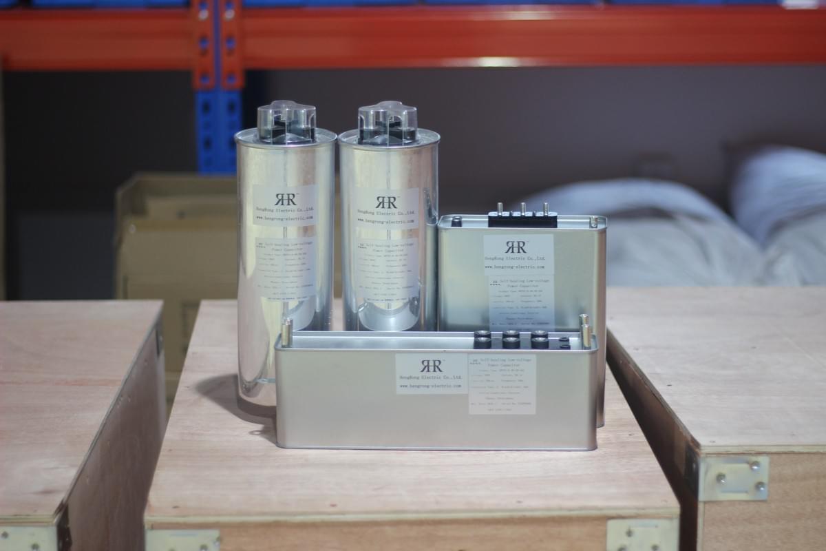
During the operation of reactive power compensation systems, capacitors are prone to various faults due to factors such as their own quality, installation operations, and environmental conditions. These faults affect the effect of reactive power compensation and may even cause safety accidents.

(I) Parallel Capacitor Faults: "Invisible Hidden Dangers" of Reactive Power Compensation

Parallel capacitors are core components of reactive power compensation systems, and they can experience a variety of faults. If a capacitor has poor insulation, it will experience leakage and intermittent flameout, resulting in a decrease in reactive power compensation efficiency. When a capacitor is open-circuited, affected by the self-induced electromotive force, the induced high-voltage electromotive force of the secondary coil decreases, making it impossible to normally increase the engine speed and directly interfering with the operation of the reactive power compensation system. A short-circuited capacitor is mostly caused by insulation breakdown. After an internal circuit short circuit, it not only damages itself but may also affect surrounding equipment. Some capacitors do not have a ground connection due to issues with their shell anti-corrosion layer design, making it impossible to form a circuit in the low-voltage circuit, causing the engine to fail to start and bringing reactive power compensation to a standstill.

At the same time, improper setting of capacitor rating values and substandard product quality are also important causes. For example, if the differential pressure protection rating of an internal fuse capacitor is set too high, it will lose its protective effect. Capacitors produced by small workshops often have problems such as damp insulation and medium aging. Under long-term operating voltage, local discharge is prone to occur, leading to insulation damage and ultimately capacitor failure, which undermines the stability of the reactive power compensation system.

(II) Group Explosion of Single Protection Fuses: "Sudden Risks" Threatening Reactive Power Compensation

Fuses are key components for protecting capacitors in reactive power compensation systems, and their group explosion can seriously affect capacitor safety. This type of fault has obvious characteristics: after a group explosion of fuses for capacitors installed outdoors, the protective tube will show signs of discharge burnout, and the protective tube and the fuse tail wire are not disconnected; group explosions are likely to occur when fuses are put into use in severe weather or when capacitors have internal defects; when a group explosion occurs, most fuses do not act, which is mostly due to the failure of the relay protection device of the reactive power compensation system.

Delving into the reasons, the design defects of the fuses themselves are an important factor. For example, after a jet-type fuse fuses, the protective tube bears an excessively high voltage; the rated current of the fuse is not matched with that of the capacitor. The rated current deviation of some fuses in China exceeds 20%, and an excessively small rated current easily leads to fusing; in addition, poor switch status of fuses and grid harmonic interference can also trigger group explosions, leaving capacitors in the reactive power compensation system unprotected and at risk of damage.

(III) Capacitor Oil Leakage and Bulging: Intuitively Visible "Fault Signals"

Oil leakage is a common fault of capacitors in reactive power compensation systems, mostly caused by backward manufacturing processes and incomplete structural design, which lead to sealing problems of capacitors during operation. The extrusion and collision of parts during transportation and substandard welding processes can also cause quality defects in capacitor shells, eventually leading to oil leakage and affecting the sealing and safety of the reactive power compensation system.

Bulging refers to the deformation of the capacitor shell. Under the action of a high electric field, the internal medium of the capacitor dissociates and discharges to the box, which, if not handled promptly, can easily cause the capacitor to explode. Poor-quality capacitors will cause the shell to expand as the temperature rises during operation, and when the heat dissipation capacity of the capacitor is insufficient, overheating will also cause bulging, seriously threatening the overall safety of the reactive power compensation system.

III. Safeguarding Reactive Power Compensation Safety: Preventive and Treatment Measures for Capacitor Faults
Self-healing Low-voltage Power Capacitor

To ensure the stable operation of reactive power compensation systems, it is necessary to take targeted measures to prevent and handle faults from aspects such as capacitor quality, installation, and operation and maintenance, so as to give full play to the role of reactive power compensation.

(I) Strictly Control Capacitor Quality: Build a "Basic Defense Line" for Reactive Power Compensation

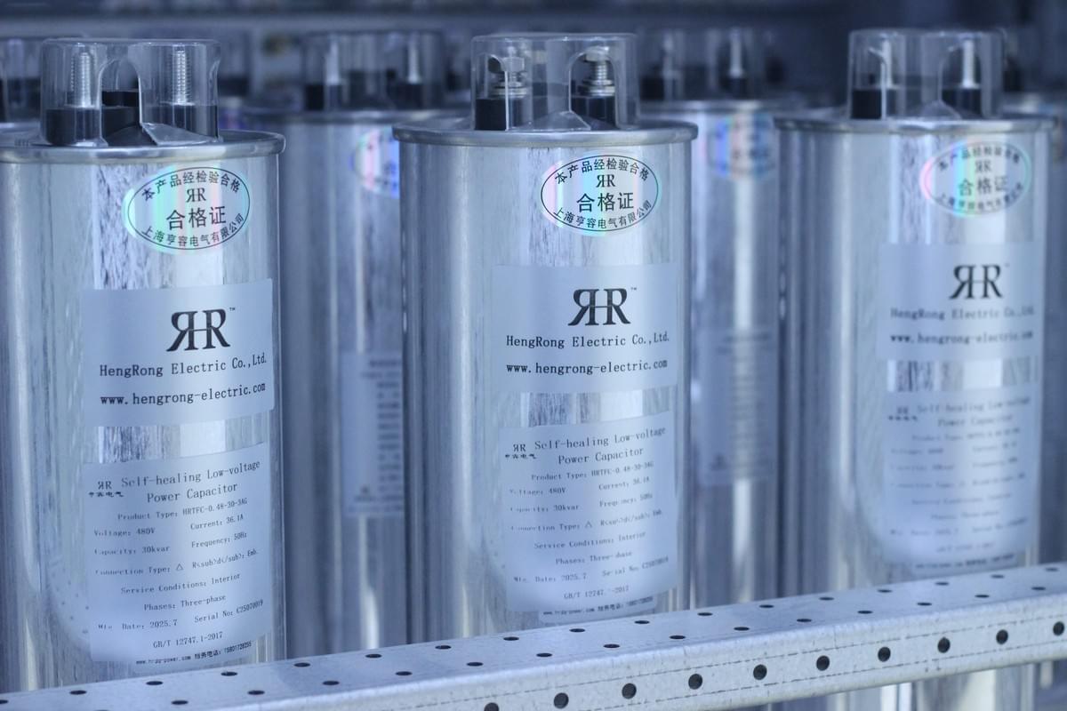
High-quality capacitors are the prerequisite for the stability of reactive power compensation systems. Enterprises should cooperate with manufacturers with strong strength and a good reputation. When purchasing, focus on checking the insulation performance and medium quality of capacitors to ensure that they meet the operating requirements of the reactive power compensation system. Before putting capacitors into use, comprehensive commissioning and acceptance should be carried out to verify indicators such as their power factor adjustment capability and voltage adaptation range. At the same time, the quality of auxiliary components such as fuses and circuit breakers should be strictly controlled to avoid affecting the operation of capacitors and reactive power compensation systems due to component problems.

(II) Scientific Installation and Configuration: Optimize the "Operating Environment" for Reactive Power Compensation

Reasonable installation is the guarantee for the stable operation of capacitors and the key to improving the effect of reactive power compensation. In terms of the wiring method of capacitor banks, a new type of secondary main wiring for high-voltage capacitors can be used instead of the traditional star or delta wiring to reduce the risk of faults; the neutral point grounding connection is strictly prohibited for discharge coils, and the wiring method should be selected in accordance with the design requirements to ensure good coordination with the capacitor protection device.

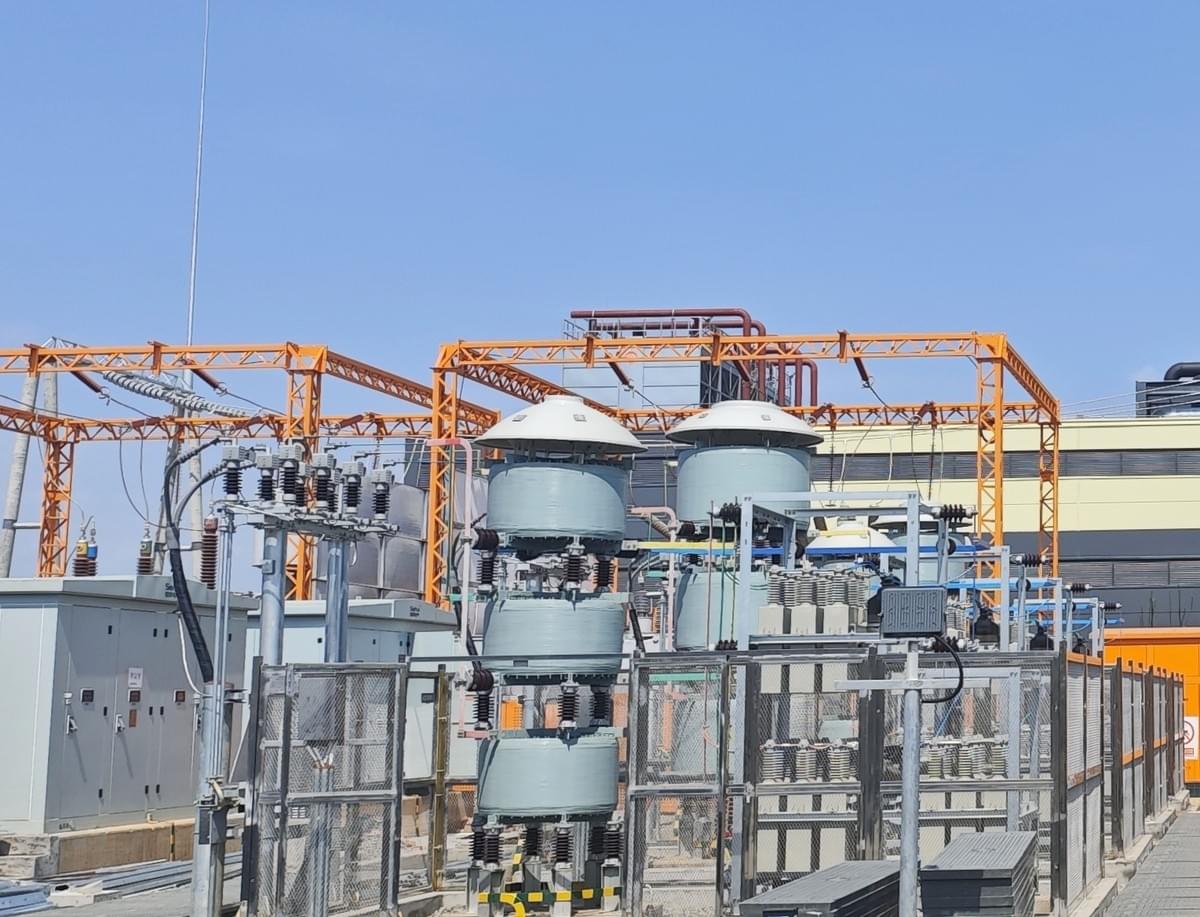
For series reactors, the reactance rate should be selected according to the background harmonic conditions of the power grid. Generally, a 5% reactance rate can be used for the 1st to 5th and above harmonics to avoid harmonic pollution damaging the capacitors and prevent "group explosion" accidents. Installers also need to check the matching between the rated current of the capacitor and the fuse to ensure a reasonable ratio, thus building a safety barrier for the reactive power compensation system from the installation link.

(III) Strengthen Daily Operation and Maintenance: Hold the "Safety Bottom Line" of Reactive Power Compensation

Daily inspections can detect hidden dangers promptly and ensure the continuous operation of the reactive power compensation system. Operation and maintenance personnel need to regularly check the cleanliness of the capacitor box, whether there is deformation and leakage, and ensure that the insulation surface is intact; focus on checking the tightness and contact status of parts, adjust loose parts promptly, and check the normal expansion and contraction of the springs of the protection device; at the same time, keep inspection records of supporting equipment such as circuit breakers and feeders to fully grasp the operating status of the reactive power compensation system.

Operators must abide by safety regulations and switch capacitor banks in accordance with the principle of "first disconnect then connect, for each circuit, first connect then disconnect"; after the circuit breaker is disconnected, it is necessary to wait for 3 minutes for full discharge before conducting inspection operations; if the relay protection device cuts off the capacitor, the fuse shall not be directly replaced and powered on before the cause is identified to avoid safety accidents.

(IV) Targeted Fault Treatment: Resolve "Sudden Crises" of Reactive Power Compensation
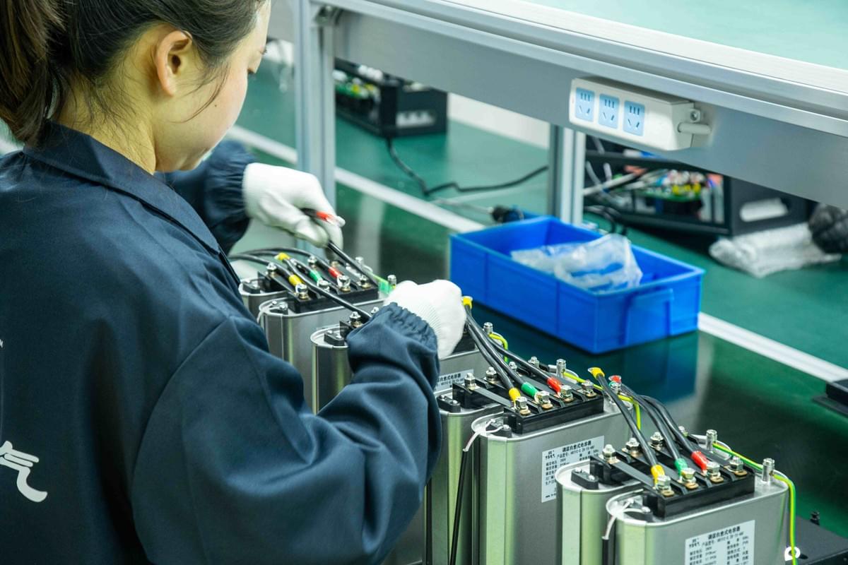
To address capacitor oil leakage, in addition to cooperating with high-quality manufacturers, capacitors should be placed upright during transportation, and it is strictly prohibited to carry the bushings; they should be handled with care. If deformation of the capacitor shell is found, the capacitor should be replaced with a new one promptly to prevent the fault from expanding. If a capacitor makes a "gurgling" sound, it is necessary to stop its operation immediately to avoid explosion; for capacitor overheating faults, the operating environment temperature should be controlled below 40°C, and an online temperature monitoring system can be used for real-time monitoring to prevent overheating from affecting the effect of reactive power compensation.

In addition, regularly test the insulation performance of capacitors with an insulation resistor to ensure that the resistance value is within a reasonable range, minimize economic losses, and comprehensively ensure the safe and stable operation of capacitors in the reactive power compensation system.

Self-healing Low-voltage Power Capacitor

Reactive power compensation and capacitors complement each other and jointly maintain the safety and efficiency of the power grid. Enterprises need to fully understand the necessity of reactive power compensation, attach importance to capacitor fault prevention and control, and through strict quality control, scientific installation, and strengthened operation and maintenance, ensure that the reactive power compensation system continues to function, provide guarantee for the stable operation of the power system, and contribute to efficient energy utilization and the sustainable development of enterprises.

Section image

At Hengrong Electrical, we understand that every detail in power control matters. From advanced product design to innovative filtering solutions, we are committed to delivering reliable, efficient, and future-ready technologies. By choosing Hengrong, you gain more than just products — you gain a trusted partner dedicated to helping your business achieve smarter, safer, and greener operations.

www.hengrong-electric.com

Previous
Innovative APF Technology: How Does the Shunt Hybrid APF...
Next
 Return to site
Cookie Use
We use cookies to improve browsing experience, security, and data collection. By accepting, you agree to the use of cookies for advertising and analytics. You can change your cookie settings at any time. Learn More
Accept all
Settings
Decline All
Cookie Settings
Necessary Cookies
These cookies enable core functionality such as security, network management, and accessibility. These cookies can’t be switched off.
Analytics Cookies
These cookies help us better understand how visitors interact with our website and help us discover errors.
Preferences Cookies
These cookies allow the website to remember choices you've made to provide enhanced functionality and personalization.
Save