
In the operation of low-voltage grids (e.g., industrial workshops, agricultural power distribution systems, commercial park power supplies), reactive power compensation serves as a core measure to improve power factor, reduce line losses, and optimize power quality. Currently, parallel capacitor banks are widely adopted for reactive power compensation in low-voltage grids. The selection of appropriate reactive power compensation methods and accurate calculation of reactive power compensation capacity directly determine the economic benefits of the compensation system and the overall operational efficiency of the grid. This article elaborates on practical solutions for reactive power compensation in low-voltage grids from four key dimensions:
- Core value of reactive power compensation
- Comparison of three optimal reactive power compensation methods
- Accurate calculation method for reactive power compensation capacity
- Comprehensive application strategy for reactive power compensation

I. Reactive Power Compensation: Core Support for Efficient Low-Voltage Grid Operation
In low-voltage grids, inductive loads such as motors, transformers, and welding machines consume significant reactive power, leading to a decline in power factor. This issue not only increases copper losses in transmission lines but also occupies transformer capacity (due to reactive power), thereby limiting the transmission of active power. Reactive power compensation addresses these challenges by providing on-site reactive power (required by inductive loads) through parallel capacitor banks. Its core value is reflected in three aspects:
1. Improve Power Factor to Avoid Penalties Related to Reactive Power
According to the Rules for Power Supply Business, industrial users with a power factor lower than 0.9 are subject to power factor adjustment penalties. By increasing the power factor to 0.9–0.95 via reactive power compensation, penalties can be completely avoided. In some regions, users with a power factor exceeding 0.95 may even qualify for electricity bill discounts or rewards.
2. Reduce Line Losses to Maximize Energy-Saving Benefits
Line losses are proportional to the square of reactive current. Reactive power compensation reduces the transmission of reactive current, thereby minimizing line losses. For example:
- Consider a low-voltage grid equipped with a 1000kVA transformer and operating 8,000 hours annually.
- After implementing reactive power compensation, annual electricity savings can reach 50,000–150,000 kWh, equivalent to 30,000–90,000 RMB (or ~4,200–12,600 USD) in electricity cost savings (based on average industrial electricity rates).
3. Release Transformer Capacity to Reduce Grid Upgrade Costs
Reactive power compensation reduces the occupation of transformer capacity by reactive loads. For instance:
- A 1000kVA transformer with a power factor of 0.8 only delivers 800kW of active power.
- After compensation (power factor increased to 0.95), the active power output rises to 950kW, eliminating the need for transformer capacity expansion to meet growing load demands.

II. Three Optimal Reactive Power Compensation Methods for Low-Voltage Grids
Reactive power compensation in low-voltage grids is primarily categorized into three types: centralized reactive power compensation, grouped reactive power compensation, and individual reactive power compensation. Each method differs in applicable scenarios and performance, requiring flexible selection based on grid structure and load distribution.
1. Centralized Reactive Power Compensation: Global Solution for Substation-Level Applications
1.1 Definition
Capacitor banks are installed on the low-voltage bus (e.g., 380V bus) of a user’s dedicated substation or distribution room. This setup centrally compensates for reactive power losses in transformers and high-voltage transmission lines, serving as the "basic configuration" for low-voltage grid reactive power compensation.
1.2 Core Characteristics
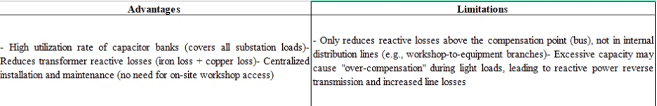
1.3 Applicable Scenarios
- Industrial users with large transformer capacity (500kVA and above) and short low-voltage distribution lines (workshops within 500 meters of the substation).
- Scenarios with concentrated loads, such as agricultural irrigation systems and rural industrial grids.
1.4 Key Parameters
- Reactive power compensation capacity: 1/3–2/3 of the grid’s average reactive power demand (to avoid over-compensation).
- Target power factor: 0.9–0.95 (industrial); 0.85–0.9 (agricultural).
2. Grouped Reactive Power Compensation: Zoned Solution for Multi-Load Points
2.1 Definition
Capacitor banks are installed in groups at workshop distribution boxes or low-voltage main line branches (based on reactive load distribution). This creates a "multi-node distributed compensation" system, balancing the advantages of centralized and individual compensation.
2.2 Core Characteristics
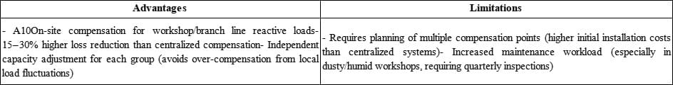
Example: A machinery factory installed grouped capacitor banks at the distribution boxes of stamping and welding workshops, reducing branch line losses by 22% compared to centralized compensation.
2.3 Applicable Scenarios
- Low-voltage grids with multiple workshops, scattered loads (e.g., large factories, industrial parks), and stable per-workshop load.
- Grids with long low-voltage distribution lines (workshops > 500 meters from the substation), where centralized compensation fails to cover end loads.
2.4 Key Parameters
- Optimal compensation point: 2/3 of the total line length (maximizes energy-saving efficiency, up to 88%+).
- Compensation capacity: 1/2–4/5 of the branch line’s full compensation demand (full demand = capacity to raise power factor to 1).
3. Individual Reactive Power Compensation: Precision Solution for High-Power Equipment
3.1 Definition
Capacitor banks are directly installed near high-power inductive loads (e.g., motors/welding machines ≥ 10kW) to compensate for the equipment’s own reactive power losses. This is the most efficient reactive power compensation method for low-voltage grids.
3.2 Core Characteristics
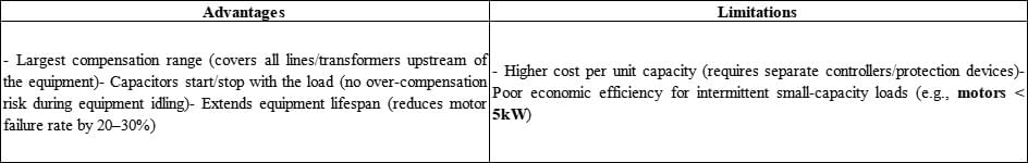
Example: For a 200kW motor, individual reactive power compensation reduces annual reactive power losses across the entire equipment link by over 10,000 kWh, with an investment payback period of just 1–2 years.
3.3 Applicable Scenarios
- High-power motors (≥ 10kW) operating continuously (8+ hours/day), such as fans, water pumps, and compressors.
- Special loads with large but concentrated reactive power fluctuations (e.g., welding machines, arc furnaces).
3.4 Key Parameters
- Compensation capacity calculation: Must be ≤ the result of "√3 × motor rated voltage (kV) × motor no-load current (kA)" (√3 ≈ 1.732, for three-phase circuit conversion).
- No-load current estimation (if data is unavailable): ~30–40% of rated current (for motors with power factor 0.85); ~35–45% of rated current (for motors with power factor 0.75–0.8).
III. Accurate Calculation of Reactive Power Compensation Capacity
The accuracy of reactive power compensation capacity calculation is critical:
- Under-compensation: Fails to meet power factor requirements (still subject to penalties).
- Over-compensation: Causes reactive power reverse transmission and equipment damage (e.g., motor insulation breakdown).
Below are calculation methods for each compensation type:
1. Centralized Reactive Power Compensation Capacity (Based on Monthly Average Load)
Step 1: Measure Average Power Factor
Install an active energy meter (records monthly active power: kWh) and a reactive energy meter (records monthly reactive power: kvarh) at the transformer’s low-voltage outlet. Calculate using:
Average power factor = 1 / √[1 + (monthly reactive power / monthly active power)²]
Example: If monthly active power = 100,000 kWh and monthly reactive power = 80,000 kvarh, average power factor ≈ 0.78.
Step 2: Define Target Power Factor
- Industrial users: 0.9–0.95
- Agricultural users: 0.85–0.9
Step 3: Calculate Compensation Capacity
- Obtain the "reactive power compensation rate" (kvar/kW) from industry tables (e.g., 0.473 kvar/kW for 0.78 → 0.95 power factor).
- Calculate average active power: Monthly active power ÷ 720 hours (average monthly operating time).
- Compensation capacity = Average active power × Reactive power compensation rate.
Example: Average active power = 100,000 kWh ÷ 720 h ≈ 138.9 kW; Compensation capacity = 138.9 kW × 0.473 kvar/kW ≈ 66 kvar (round to standard capacity).
2. Individual Reactive Power Compensation Capacity (Based on Motor No-Load Characteristics)
Use the same logic as the "key parameters" for individual compensation:
Compensation capacity ≤ √3 × motor rated voltage (kV) × motor no-load current (kA)
If no-load current data is unavailable, use one of two estimation methods:
Maximum torque multiple method:
No-load current = Rated current × [sin(φₙ) – cos(φₙ) / (2×b)]
- φₙ = motor rated power factor (e.g., sin(0.85) ≈ 0.527)
- b = maximum torque multiple (1.8–2.2, from motor specs).
Empirical formula:
No-load current = Rated current × cos(φₙ) × [2.26 – (K×cos(φₙ))]
- K = 2.1 (or 2.15 if cos(φₙ) > 0.85).
3. Grouped Reactive Power Compensation Capacity (Based on Line Load Distribution)
Follow these core principles:
- Single branch line: Compensation point at 1/2–4/5 of the line length; capacity = 1/2–4/5 of full compensation demand.
- Multiple branch lines: Calculate capacity for each branch individually; total capacity = sum of branch capacities (avoids reactive power reverse transmission between branches).
IV. Comprehensive Application Strategy for Reactive Power Compensation
A single compensation method cannot cover all low-voltage grid scenarios. We recommend a hierarchical strategy:
- Prioritize Individual Compensation
Deploy individual capacitor banks for high-power continuous loads (≥ 10kW motors, welding machines) to minimize reactive losses across the entire equipment link.
- Supplement with Grouped Compensation
Install grouped systems at workshop distribution boxes to cover medium/small loads (5–10kW motors, lighting, sockets) and fill gaps left by individual compensation.
- Backup with Centralized Compensation
Use centralized compensation on the substation’s low-voltage bus to:
- Compensate for transformer and high-voltage line reactive losses.
- Adjust capacity dynamically during local load fluctuations (acts as a backup for grouped/individual systems).
Conclusion: No "One-Size-Fits-All" Reactive Power Compensation
The "best" reactive power compensation method depends on grid-specific conditions, including:
- Load type (proportion of inductive loads, equipment power).
- Line length (branch distance, main line total length).
- Operating conditions (equipment start-stop frequency, load fluctuation range).
Whether choosing centralized (global protection), grouped (zoned optimization), or individual (precision efficiency) compensation, the core goal is to balance power factor compliance, line loss reduction, and investment cost control through scientific design.

If you need a customized reactive power compensation solution (e.g., capacity calculation, method selection) for your low-voltage grid, please leave a message below with details. Hengrong Electric CO., LTD. will provide a personalized solution tailored to your needs!