
In industrial AC power grids, the widespread use of power electronic devices such as rectifiers and thyristor-controlled circuits frequently causes power quality issues like harmonic distortion, reactive power imbalance, and voltage fluctuations. These problems not only increase equipment losses but also may lead to production interruptions. As the core component of UPQC (Unified Power Quality Conditioner), APF (Active Power Filter) works in synergy with UPQC to provide an all-in-one solution for power quality problems. Combining laboratory test data, this article elaborates on how APF empowers UPQC to deliver stable and efficient power quality assurance for AC power grids, covering APF’s functional positioning, topological design, compensation effects, and application key points.

I. AC Power Grid Pain Points: Targeted Solutions by APF
Industrial AC power grids face complex and diverse power quality issues, which are difficult to fully address with a single device. As the core functional module of UPQC, APF can accurately tackle the following key pain points:
1. Harmonic Pollution: APF Reduces Equipment Loss
Nonlinear loads such as rectifiers and frequency converters generate odd-order harmonics (3rd, 5th, 7th, etc.), significantly increasing the Total Harmonic Distortion of current (THDi). Laboratory tests show that the THDi of a six-pulse bridge rectifier load reaches 27%, with the 3rd harmonic accounting for 14.19%, the 5th harmonic for 21.35%, and the 13th/15th harmonics each exceeding 2%. High harmonic content increases iron core losses in motors and transformers, accelerates insulation aging, and raises equipment failure rates by over 30%. However, APF can collect load current in real time, generate a compensating current with equal magnitude but opposite direction to the harmonic current, and fundamentally cancel harmonics to prevent equipment damage caused by harmonics.
2. Reactive Power Imbalance: APF Improves Power Factor
Industrial loads (e.g., asynchronous motors, reactors) consume large amounts of reactive power, resulting in low grid power factor. Laboratory data indicates that the three-phase power factors of a certain RL-type nonlinear load are 0.96 (Phase A), 0.90 (Phase B), and 0.83 (Phase C) respectively, with the lowest value far below the 0.9 standard required for industrial users. A low power factor not only exposes enterprises to electricity fee fines but also increases line current, raising line losses by approximately 35%. APF (especially the shunt APF in UPQC) can detect reactive power demand in real time, quickly output reactive compensating current, and uniformly increase the power factor to above 0.95, thereby avoiding fines and reducing line losses.
3. Voltage Issues: APF Ensures Stable Power Supply
AC power grids often experience voltage sags, fluctuations, and three-phase asymmetry. Laboratory simulations show that when the grid voltage sags by 10% (duration: 200ms), precision equipment (e.g., PLCs) malfunctions; if the Phase B voltage sags by 20% and Phase C by 40%, it also causes three-phase load current imbalance and abnormal motor operation noise. The series APF in UPQC can quickly inject compensating voltage into the grid through a series injection transformer to offset voltage sags and fluctuations, stabilizing the load-side voltage within ±2% of the rated value and ensuring continuous operation of production equipment.
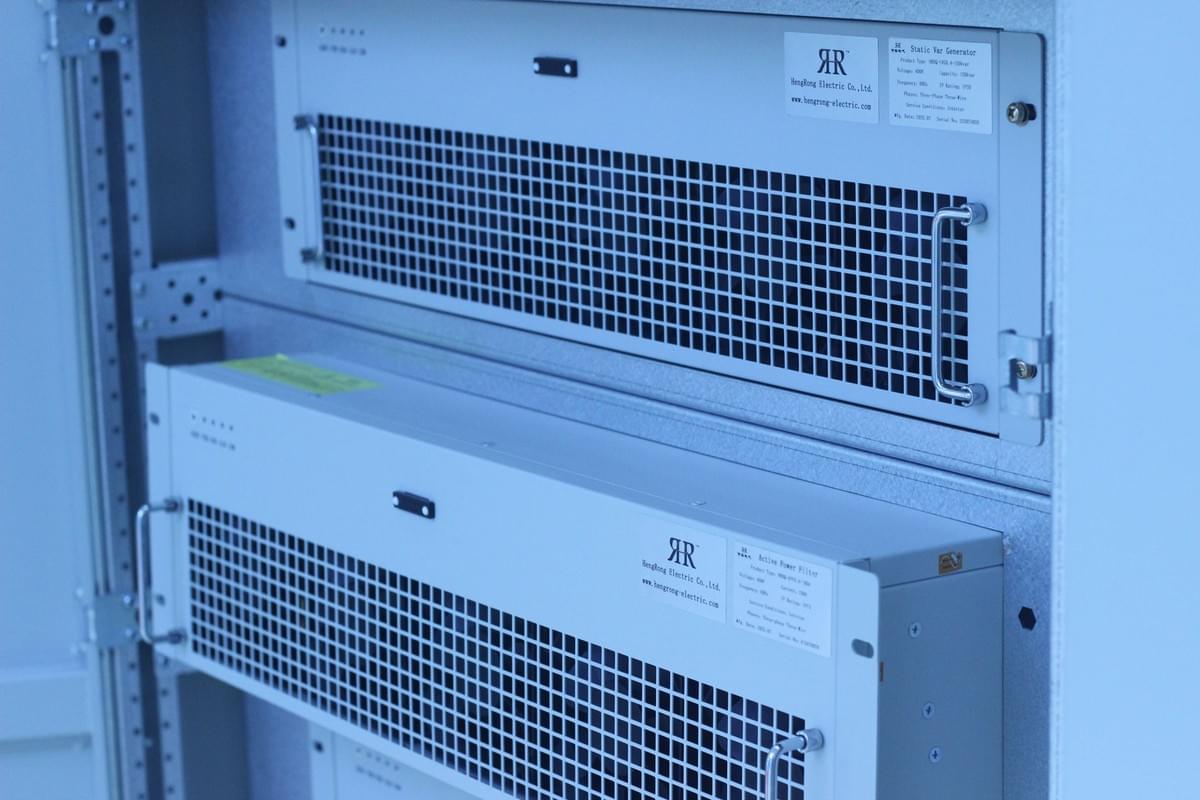
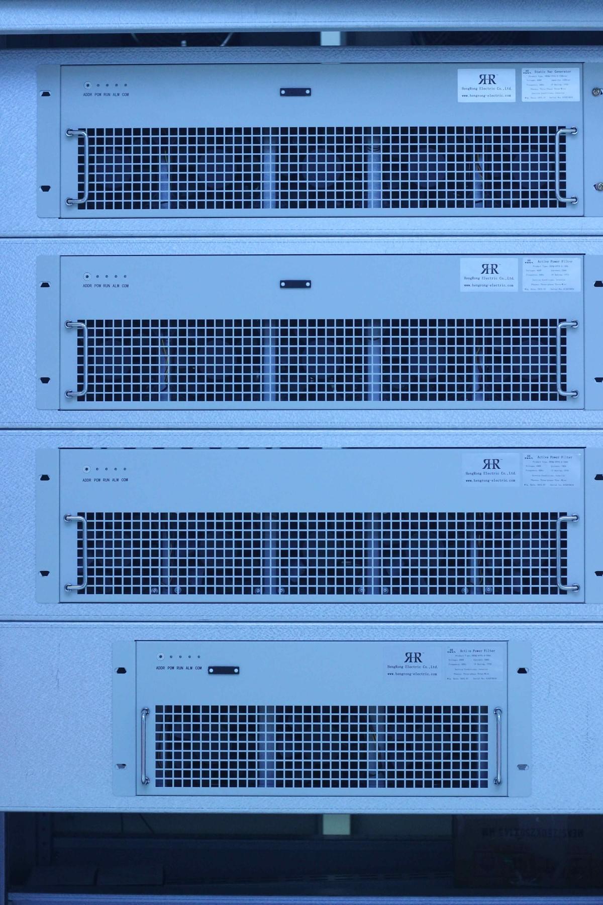
II. Core of UPQC Topology: Functional Division and Collaborative Logic of APF
UPQC is essentially an integrated system of "series APF + shunt APF", with energy interaction realized through a DC link. The topological design and functional division of APF directly determine the effectiveness of power quality management:
1. Dual Roles of APF: Collaboration Between Series and Shunt Configurations
UPQC consists of two Voltage Source Inverters (VSIs), which act as series APF and shunt APF respectively. Their specific functions are as follows:
- Shunt APF: Connected in parallel with the load, it collects load current, separates harmonic current and reactive current using the instantaneous reactive power theory, and then injects reverse compensating current into the grid. Its core functions include: filtering load harmonics (reducing THDi from 27% to 2.38%), compensating reactive power (increasing power factor to above 0.95), and balancing three-phase currents (improving current symmetry to over 98%);
- Series APF: Connected to the grid via a series injection transformer, it collects grid voltage signals. When voltage harmonics, sags, or asymmetry are detected, it quickly generates and injects compensating voltage into the grid to ensure stable load-side voltage waveform. For example, if the grid voltage contains 10% of the 3rd harmonic, the series APF can inject reverse 3rd harmonic voltage, reducing the Total Harmonic Distortion of voltage (THDu) at the load side from 11.36% to 1.89%;
- Collaborative Advantage: A single APF can only solve one type of problem (e.g., shunt APF cannot handle voltage sags). However, the series and shunt APFs in UPQC achieve energy complementarity through DC capacitors, enabling simultaneous management of current and voltage issues and covering all scenarios of power quality improvement.
2. Topological Classification of APF: Adapting to Different Grid Scenarios
Based on the relative position of APF and the load, UPQC is divided into two mainstream topologies to meet the needs of different industrial scenarios:
- UPQC-L Topology: The series APF is close to the load side, and the shunt APF is close to the grid side. This topology prevents the transformer from bearing harmonic currents and reactive power, reduces transformer losses, extends its service life, and is suitable for old industrial plants with limited transformer capacity;
- UPQC-R Topology: The shunt APF is close to the load side, and the series APF is close to the grid side. Since the shunt APF is closer to the load, it has a faster response speed (≤50μs) to load current changes, making it suitable for scenarios with frequent load fluctuations (e.g., welding machines, punch press production lines);
- Three-Phase Four-Wire Adaptation: For grids that need to connect both single-phase and three-phase loads (e.g., mixed power supply scenarios in industrial parks), UPQC draws a neutral line through a voltage divider in the DC link, ensuring that harmonics and reactive power generated by single-phase loads (e.g., lighting, small motors) can also be accurately compensated by APF.
III. APF Compensation Effects: Verified by Laboratory Test Data
Extensive laboratory tests have verified the excellent compensation effects of APF in UPQC systems, with key data as follows:
1. Harmonic Filtering: APF Significantly Reduces THD
A six-pulse bridge rectifier was used as the nonlinear load in the test. Without APF, the load-side voltage THDu was 11.36% (10% for 3rd harmonic, 5% for 5th, 2% for 7th), and current THDi was 27% (14.19% for 3rd harmonic, 21.35% for 5th, 2.26% for 13th). After APF was put into operation:
- Voltage Harmonics: THDu decreased to 1.89%, with the 3rd harmonic dropping to 0.42%, 5th to 1.62%, and 7th to 1.50%. The proportion of each harmonic was below 2%;
- Current Harmonics: THDi decreased to 2.38%, with the 3rd harmonic dropping to 0.42%, 5th to 1.62%, and 13th to 0.19%, fully complying with the power quality requirements of the PN-EN 50160 standard.
2. Reactive Power and Current Balance: APF Optimizes Grid Parameters
For the RL-type unbalanced load, without APF, the three-phase power factors were 0.96, 0.90, and 0.83, with a three-phase current difference exceeding 20%. After APF was put into operation:
- Power Factor: All three-phase power factors were increased to above 0.95, meeting the power factor standard for industrial users and avoiding electricity fee fines;
- Current Balance: The three-phase current waveforms became symmetrical, with the three-phase current difference dropping to below 3%. Line losses were reduced by approximately 30%, and the DC link voltage remained constant without obvious fluctuations.
3. Voltage Management: APF Stabilizes Load-Side Voltage
The laboratory simulated various voltage problems to verify the compensation capability of APF:
- Voltage Sag: When the grid voltage sagged by 10% (duration: 200ms), the series APF injected compensating voltage within 20ms, stabilizing the load-side voltage at over 99% of the rated value without equipment shutdown;
- Voltage Fluctuation: After superimposing a 2.5Hz, 20%-amplitude voltage fluctuation on the grid, the series APF quickly offset the fluctuation, controlling the load-side voltage fluctuation amplitude within ±2%;
- Three-Phase Asymmetry: When simulating a 20% voltage sag in Phase B and 40% in Phase C, the series APF achieved three-phase independent compensation, increasing the load-side three-phase voltage symmetry to over 98% and ensuring smooth motor operation without abnormal noise.
IV. Key Application Points of APF: Ensuring Stable Operation of UPQC
To give full play to the role of APF in UPQC, the following application key points should be noted based on technical practice conclusions:
1. Topology Selection: Matching Grid and Load Characteristics
- If the transformer capacity is limited or needs to be extended, the UPQC-L topology should be preferred. The series APF isolates load harmonics and reactive power to reduce the transformer load;
- If the load fluctuates frequently (e.g., high-frequency punch presses in production lines), the UPQC-R topology should be selected. The shunt APF close to the load enables faster current response;
- For three-phase four-wire grids, a UPQC topology with a neutral line should be used to ensure that power quality issues of single-phase loads can also be effectively resolved by APF.
2. Parameter Matching: APF Capacity and Filtering Adaptation
- APF Capacity Calculation: The shunt APF capacity should cover the maximum harmonic current and reactive power demand (e.g., for a harmonic current of 100A and reactive power demand of 200kvar, a 250kvar capacity should be selected to reserve a 10%-20% margin); the series APF capacity should match the maximum voltage compensation amplitude (e.g., if the grid voltage sag is 15%, the APF rated voltage should be ≥15% of the grid voltage);
- Filter Parameter Design: APF should be equipped with an LC low-pass filter to filter out high-frequency harmonics (e.g., components above 10kHz) generated during its own switching process, avoiding secondary pollution to the grid. The filter cutoff frequency is usually set to 5-10 times the grid frequency (e.g., 250-500Hz for a 50Hz grid) to balance filtering effect and system stability.
3. Control Strategy: Improving APF Response Speed
- Adopt a "feedforward + feedback" composite control strategy: Feedforward control can quickly track changes in load current and grid voltage (e.g., adjusting the compensating current within 0.1ms when the load current changes suddenly), while feedback control corrects compensation deviations to ensure compensation accuracy (error ≤2%);
- Optimize the harmonic detection algorithm: Priority should be given to the detection algorithm based on the instantaneous reactive power theory to ensure detection accuracy (error ≤1%) for major harmonics (3rd, 5th, 7th, etc.), providing a basis for APF to generate accurate compensating signals.
V. Conclusion: APF – The Core of UPQC for AC Power Grid Optimization
In the power quality management of industrial AC power grids, APF is the core of UPQC for realizing full-scenario management of "harmonic filtering + reactive power compensation + voltage stabilization". Laboratory data shows that the synergy between APF and UPQC can significantly reduce THD, improve power factor, and stabilize grid voltage, meeting the high-quality power requirements of the PN-EN 50160 standard.
If your AC power grid is facing issues such as excessive harmonics, voltage sags, or power factor fines, please feel free to provide information such as grid type (e.g., three-phase three-wire/four-wire), load characteristics (e.g., rectifier power, number of motors), and key pain points (e.g., voltage sag frequency, THD value). Hengrong Electric CO., LTD. will customize an exclusive AC power grid quality optimization solution for you based on APF technology!