With the continuous growth of industrial production and residential electricity demand, the stable operation of power grids and the reliability of power supply have become core priorities. However, the imbalance of reactive power, a key issue affecting power grid efficiency, has long plagued low-voltage distribution systems. Traditional reactive power compensation devices are not only structurally complex and difficult to maintain, but also generate massive inrush currents during switching, which shorten the service life of power capacitors, cause frequent failures, and increase the electricity costs for enterprises. To address these issues, we have developed a new type of intelligent power capacitor with high integration, zero inrush current characteristics, and cost-effectiveness based on zero-crossing switching technology, providing an efficient solution for reactive power compensation in low-voltage power grids.

I. Pain Points of Traditional Reactive Power Compensation: Three Core Challenges Faced by Power Capacitors

- High Risk of "Single Point Failure" in Controllers: Most traditional devices adopt a "one controller managing multiple power capacitors" model. Once the controller malfunctions, the entire device shuts down, and power capacitors are prone to burnout due to loss of control, resulting in economic losses and power grid outages.
- Switching Inrush Currents Shorten the Service Life of Power Capacitors: During switching with traditional switches, there is often a significant difference between the grid voltage and the residual voltage of power capacitors. According to the power capacitor characteristic equation \(i_{C}=C \frac{d u_{C}}{d t}\), sudden voltage changes trigger massive inrush currents. This impact not only may damage thyristors but also accelerates the aging of power capacitors. Experimental data show that the failure rate of power capacitors with non-zero crossing switching is much higher than that with zero-crossing switching, and their service life can be shortened by up to 50%.
- Low Device Integration and High Maintenance Costs: Traditional reactive power compensation systems consist of scattered components such as controllers, switches, and power capacitor banks. They have complex wiring, occupy a large space, and troubleshooting faults in each component is difficult. Daily maintenance requires significant labor and time costs.
II. Core Breakthrough: Zero-Crossing Switching Technology Enables "Zero Inrush Current Switching" for Power Capacitors

1. Core Principle of Zero-Crossing Switching
- Ideal Switching State: If the power capacitor is pre-charged to the peak value of the power supply voltage and switched at the peak of the power supply voltage, the voltage change rate is zero, the initial value of the current \(i_{c}\) is zero, and it rises steadily according to a sinusoidal law thereafter, with no impact throughout the process.
- Optimization for Practical Applications: Considering factors such as fluctuations in power grid parameters and the difficulty of maintaining the power capacitor voltage at the peak value continuously, we have optimized the design to "connect the power capacitor when the grid voltage is zero". Meanwhile, after the power capacitor is disconnected, it is quickly discharged through a dedicated resistor to ensure that the residual voltage of the power capacitor is close to zero before the next switching, eliminating the generation of inrush currents in practical scenarios.
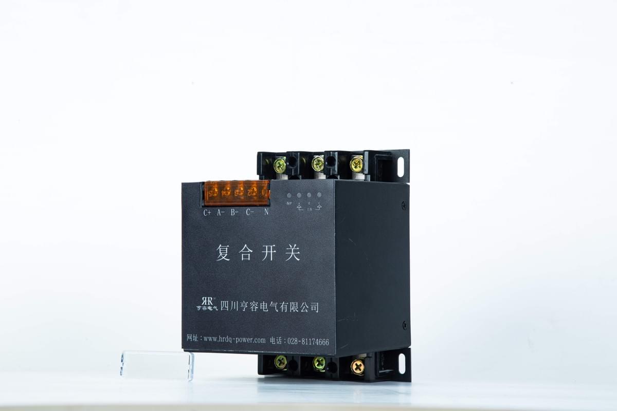
2. Composite Switch: The "Reliable Steward" for Power Capacitor Switching
- Switching Moment: When the controller detects that the voltage across the thyristor is zero, it immediately sends a trigger pulse, and the bidirectional thyristor turns on quickly, ensuring that the power capacitor is connected without inrush current.
- Normal Operation Phase: After the power capacitor is connected, the latching relay takes over from the thyristor to maintain the on-state. Compared with thyristors, latching relays have no conduction loss, which can avoid device overheating damage caused by long-term operation and further protect the operating environment of the power capacitor.
- Disconnection Process: When the controller issues a disconnection command, it first turns off the latching relay, and the thyristor automatically turns off when it detects that the current is zero. At the same time, the resistance discharge circuit is activated to quickly reduce the residual voltage of the power capacitor to zero, preparing for the next switching.
III. System Design: A Highly Integrated Intelligent Architecture for "Autonomous Control" of Power Capacitors

1. Intelligent Controller: The "Brain Center" of the Power Capacitor
- Real-Time Parameter Collection and Calculation: It collects three-phase voltage and current signals of the power grid through voltage transformers and current transformers. After conversion by a 12-bit A/D converter, it uses a fast FFT algorithm to calculate key parameters such as voltage effective value, current effective value, reactive power, and power factor.
- Intelligent Switching Decision-Making: Based on the preset control strategy and combined with real-time power grid parameters, it automatically determines whether the power capacitor needs to be switched and precisely controls the action of the composite switch.
- Multi-Machine Collaborative Management: A single power capacitor can operate independently, and multiple power capacitors can be connected via the RS485 interface to form a large-capacity reactive power compensation system. Even if the controller of one power capacitor malfunctions, it will not affect the normal operation of other power capacitors, completely solving the "single point failure" problem of traditional solutions.
2. Full-State Monitoring: "Transparent" Operation of Power Capacitors
- It intuitively displays parameters such as three-phase voltage, current, and power factor, making it convenient for staff to grasp the power grid compensation effect at any time.
- It has alarm functions for overvoltage, overcurrent, power capacitor faults, etc. Once an abnormality occurs, it immediately issues a prompt to facilitate quick problem location.
- It supports switching between phase-by-phase compensation and three-phase compensation, which can be flexibly adjusted according to the load characteristics of the power grid to ensure the compensation accuracy of the power capacitor.
IV. Simulation and Experimental Verification: Stable Performance of Power Capacitors with Significant Zero Inrush Current Effect

1. Simulation Test: Zero Inrush Current for Power Capacitors in Different Scenarios
- Scenario with Residual Voltage: When the power capacitor is pre-charged to the peak value of the power supply voltage, the phase A voltage waveform is stable without sudden changes when it is connected, and the current waveform rises sinusoidally from 0, with no inrush current.
- Scenario without Residual Voltage: When the residual voltage of the power capacitor is zero, the phase A voltage and current waveforms are also stable when it is connected, consistent with the scenario with residual voltage. This proves that as long as zero-crossing switching is achieved, no inrush current will be generated for the power capacitor regardless of the residual voltage status.
2. Actual Experiment: Stable Performance in Industrial-Scale Scenarios
- Voltage waveform: No step change occurred at the moment of connection, and it remained sinusoidally stable throughout the process.
- Current waveform: The initial value was close to zero, with no impact peak, and it followed the voltage change steadily.
- Disconnection and Discharge: After the power capacitor was disconnected, it was discharged through a resistor, and the residual voltage dropped to near zero within a short time, preparing for the next switching.
V. Application Value: Intelligent Power Capacitors Reduce Costs and Increase Efficiency for Low-Voltage Power Grids

- Extend the Service Life of Power Capacitors and Reduce Replacement Costs: Zero inrush current switching reduces the impact damage to power capacitors, extending their service life by 30%-50% compared with traditional solutions and reducing the costs incurred by enterprises due to power capacitor replacement.
- Improve Power Grid Stability and Reduce Energy Consumption: Precise reactive power compensation can improve the power factor of the power grid and reduce line losses. Experimental data show that the average energy consumption of the power grid can be reduced by 5%-10% after application.
- Simplify Maintenance and Save Labor Costs: The highly integrated design reduces the volume of the device by 40%. Additionally, with its intelligent alarm and status monitoring functions, maintenance efficiency is improved by more than 60%.
- Flexible Expansion to Adapt to Different Scenarios: A single power capacitor can operate independently, and multiple power capacitors can be networked via RS-485. The capacity can be flexibly increased according to the growth of power grid load, making it suitable for different low-voltage distribution scenarios such as factories, shopping malls, and residential communities.
Conclusion