Abstract:With the gradual replacement of overhead power supply lines by cable power supply lines, the reactive power compensation method has also developed from the traditional capacitor compensation to the combination compensation of reactance and capacitance. With the development of power electronic technology, dynamic reactive power compensation devices represented by SVC and SVG have a tendency to replace the reactance-capacitance combination compensation. Combined with a certain LNG receiving station project, this paper discusses the reactive power compensation method of the receiving station.
Keywords:long-distance cable transmission; reactive power compensation; reactor; SVC; SVG
0 Introduction
LNG (Liquefied Natural Gas) receiving stations are often far away from the public power grid due to their remote geographical locations. At present, power cables are gradually replacing traditional overhead lines in the construction of power supply lines, which makes long-distance cable transmission the main form of the external power supply project of LNG receiving station projects. Corresponding to this trend, the reactive power compensation method for the 6 kV system in the receiving station has also developed from the traditional capacitor compensation to the combination compensation of reactance and capacitance.

In recent years, with the rapid development of power electronic technologies and products, the maturity of related equipment has significantly increased. Dynamic reactive power compensation devices represented by SVC (Static Var Compensator) and SVG (Static Var Generator) have been widely used due to various significant advantages. SVG has a good market prospect in LNG receiving stations and even the petrochemical industry because of its advantages such as continuous adjustment from inductive to capacitive, fast response speed, and continuous absorption of reactive power.
1 Main Reactive Power Compensation Devices
The main reactive power compensation methods in power systems include: capacitor compensation, reactor compensation, SVC device compensation, and SVG device compensation.
1.1 Capacitors
(1) Principle of capacitor reactive power compensation:The electrical equipment (load) in the power system will generate inductive reactive power during use, which will reduce the efficiency of the power supply capacity. This situation can be improved by appropriately adding capacitors to the system. Because a large number of inductive loads in the circuit will cause a phase deviation in the power grid (inductive components will make the AC current phase lag, and the voltage phase lead by 90°). The characteristics of capacitors in the circuit are opposite to those of inductors, which can absorb the reactive power generated by inductive loads and thus play a compensating role.
(2) High-voltage capacitor reactive automatic compensation device:The high-voltage capacitor bank reactive automatic compensation device suitable for 6 kV and 10 kV systems can automatically switch capacitor banks through comprehensive calculation according to factors such as system voltage and reactive power deficit, so as to improve voltage quality, improve power factor and reduce line loss. This type of device is the most mature and widely used reactive power compensation device, and is generally used in the power systems of petrochemical, chemical, and steel industries. In the automatic mode, the reactive power compensation controller realizes the compensation of the system's inductive load by controlling multiple contactors to switch one or several groups of capacitors among multiple groups.
1.2 Reactors
Reactors rely on the inductive reactance of the coil to hinder the change of current in the circuit. The functions of reactors in the power system include current limiting, voltage reducing, compensation, etc. Parallel reactors are widely used in 220 kV, 110 kV, 10 kV, 6 kV and other levels of power grids to absorb the charging capacitive reactive power of cable lines and improve the operation status of the power system related to reactive power. Reactors are divided into three types according to their structural types.
(1) Iron-core reactors:Iron-core reactors are divided into oil-immersed and dry-type. Their advantages are high operational stability, low loss, small floor area, less magnetic leakage, and easy on-line monitoring and condition-based maintenance. The disadvantages are that they may suffer from magnetic saturation due to overvoltage, overcurrent and harmonics, and have low short-circuit current resistance. In addition to the above disadvantages, dry-type iron-core reactors cannot operate outdoors.
(2) Dry-type air-core reactors:They have good linearity, low operating noise, strong overcurrent capacity, strong heat dissipation capacity, simple and robust mechanical structure, can be used indoors and outdoors, and are basically maintenance-free. The disadvantages are large volume, large loss, and large magnetic leakage. Sufficient installation space must be considered during installation to prevent magnetic leakage from affecting other equipment and personnel safety.
(3) Semi-core reactors:Semi-core reactors are a new type of reactor between iron-core reactors and air-core reactors. A core with an unclosed magnetic circuit is added to the winding of the air-core reactor, so that the semi-core reactor has the advantages of both iron-core reactors and air-core reactors. The coil diameter of the semi-core reactor is 20% smaller than that of the air-core reactor, the reactor loss is 25% lower, the linearity is close to a straight line, the impedance does not decrease with the increase of current, and the noise is lower than 50 dB.
An ideal reactor should have the characteristics of no oil, no noise, small size, good linearity, no magnetic leakage, and strong overcurrent capacity. The future development direction of reactors is dry-type semi-core magnetic shield reactors, which are also the direction that various reactor manufacturers are striving to improve and optimize.
1.3 SVC
SVC is a static var compensator. SVC can be regarded as a dynamic reactive power source. According to the needs of accessing the power grid, it can provide reactive power (capacitive) to the power grid or absorb excess reactive power (inductive) from the power grid. Connecting a capacitor bank (usually a filter bank) to the power grid can provide reactive power to the grid; when the grid does not need too much reactive power, the excess capacitive reactive power is absorbed by a parallel air-core reactor.
Compared with traditional capacitor and reactor compensation methods, static var compensators can achieve fast and smooth adjustment to meet the needs of dynamic reactive power compensation, and can also achieve phase-by-phase compensation. It has strong adaptability to three-phase unbalanced loads and impact loads.
1.4 SVG
SVG (Static Var Generator), also known as dynamic reactive power compensation generator. SVG performs dynamic reactive power compensation through a self-commutated bridge converter, and is a new product in the field of reactive power control.
Working principle of SVG:With a high-power voltage-source inverter as the core, by adjusting the output voltage of the inverter to form an adjustable fundamental voltage difference or harmonic voltage difference with the system voltage, it controls the reactive current or harmonic current injected into the system.
SVG is a product developed on the basis of SVC. Compared with SVC, SVG has the following main characteristics and advantages: ① fast response speed; ② low operating loss; ③ greatly improved operational safety performance; ④ small floor area; ⑤ convenient operation and maintenance.

However, as a newly developed product in recent years, the maturity and performance of SVG still need to be further improved. It is believed that with the continuous progress of power electronic technology, SVG products can achieve high reliability and maturity and become the mainstream products in the field of reactive power compensation.
2 Power Distribution System and Reactive Power Compensation Method of a Certain LNG Receiving Station Project
(1) Voltage level of the power distribution system:110 kV/6 kV/380 V.
(2) 110 kV external line configuration:There are two 110 kV lines in the 110 kV external line project, which are supplied in a 1-main-1-standby mode. The main power supply line is connected from the upper-level 220 kV station to the 110 kV station GIS (Geographic Information System) through a full cable loop. The standby power supply line is T-connected from the 110 kV overhead line of the power company and connected to the 110 kV station GIS by means of overhead line to cable.
(3) Reactive power compensation method:The incoming cable of the 110 kV external line project of the project is about 13 km long, and the charging power of this section of cable is about 8.2 MVar. To ensure that the power factor on the power supply side is > 0.9 even under low load conditions in the early stage of commissioning, the reactive power of the 110 kV external cable is compensated on the 6 kV side, with one 7 MVar reactor and one 6 MVar reactor configured. In addition, as a means to compensate for the inductive reactive power of other loads in the system, two 3 MVar 6 kV capacitor banks are also configured.
(4) Significance of reactive power compensation:In the early stage of the project commissioning, the total active power of the plant is very low relative to the reactive power of the external cable, which makes the power factor on the 110 kV power supply side very low without compensation. At this time, the compensation of the reactor is very important.
It has been observed that when the total load of the plant is very low, after putting into operation the 7 MVar reactor, the power factor on the 110 kV power supply side can be increased from 0.2 to about 0.9, avoiding huge reactive power consumption and corresponding electricity fees. The 110 kV external line project of the L project near a certain LNG receiving station project is configured with two cable lines with a length of about 10 km. Since the L project is not equipped with reactors, in the early stage of commissioning, more than 1 million RMB or even higher reactive power electricity fees will be generated every month. Therefore, when long-distance cable power supply is adopted for the 110 kV external line, it is of great significance to configure reactors for reactive power compensation on the 6 kV side.
3 Installation and Commissioning of Reactive Power Compensation Devices in the Power Distribution System of a Certain LNG Project
The installation and commissioning contents of the reactive power compensation devices in the power distribution system of a certain LNG receiving station project include: installation and commissioning of 6 kV reactors, installation and commissioning of 6 kV capacitors, and switching control of capacitors and reactors during project operation.
3.1 Selection and Peripheral Design of 6 kV Reactors
Reactors can be divided into iron-core reactors, air-core reactors and semi-core reactors according to their structural types. During the procurement process of the project, dry-type air-core reactors were selected because of their low cost, large output and ease of procurement. Dry-type air-core reactors have many advantages, but their prominent disadvantage is large magnetic leakage. It is difficult to accurately calculate the magnetic leakage of air-core reactors quantitatively, but the magnetic leakage field of the reactor during operation can be seen from the manufacturer's simulation software.
To avoid the influence of magnetic leakage from air-core reactors on surrounding equipment, manufacturers will generally provide a description of safety distance requirements. Taking the 3-layer stacked dry-type air-core reactor used in a certain LNG project as an example, the manufacturer's data requires the magnetic distance as follows: ① Within 1.1 times the diameter around the dry-type air-core reactor, there shall be no closed metal rings to avoid heating due to circulation; ② There shall be no closed metal rings within 1/2 diameter above and below the dry-type air-core reactor; ③ The minimum distance between the dry-type air-core reactor and other air-core reactors is 1.7 times the reactor diameter.
During the design and construction process, the minimum magnetic distance must be ensured in strict accordance with the manufacturer's requirements. The following 4 points should be noted:
(1) If dry-type air-core reactors are used, sufficient space should be arranged outdoors for reactor installation, and it is best to install the three-phase coils of the reactor in an in-line or delta arrangement to minimize the mutual influence between the three-phase coils.
(2) The foundation of dry-type air-core reactors should generally use plain concrete. If the strength of plain concrete cannot meet the requirements, insulation measures should be taken at the steel intersections of reinforced concrete to prevent the formation of closed loops when the steel bars cross.
(3) The equipment grounding of dry-type air-core reactors must adopt single-point grounding to prevent the grounding wire from forming a closed loop through the ground network when two-point grounding is adopted, which is a special feature of the grounding design of dry-type air-core reactors.
(4) There should be no metal closed loops within a certain distance around the air-core reactor (specific data according to the manufacturer's technical requirements) to avoid circulation induced by magnetic leakage. In addition, there should be as few magnetically conductive metals as possible within a certain distance around to avoid eddy currents induced by magnetic leakage. When metal materials must be used (such as making reactor grounding rings), weak magnetic materials should be considered.
3.2 Automatic Switching Control of 6 kV Reactive Power Compensation Devices
During the operation stage, how to reasonably and efficiently switch 6 kV reactors and capacitor banks to maximize the role of reactive power compensation devices is an important issue that operators need to consider.
(1) Current switching method:According to the design idea, a 7 MVar reactor is configured on the 6 kV side to compensate for the reactive power of the 13 km long 110 kV external cable, and 6 kV capacitors are used to compensate for the inductive load of the 6 kV system.
- In the early stage of power reception of the project, there is basically no load in the whole plant. At this time, one 7 MVar reactor is put into operation, and the other reactor and all capacitors are not put into operation;
- In the early stage of project start-up, the whole plant has only a small inductive load (air conditioners, lighting, small pumps, etc.). At this time, it is considered to put into operation one 6 MVar reactor, and the reactor and the inductive load jointly compensate for the reactive power of the 110 kV external cable;
- When the project is officially put into production and a large amount of gas is exported, the inductive load of the whole plant increases significantly. If only one 6 MVar reactor is put into operation at this time, inductive over-compensation will occur, resulting in a decrease in the power factor on the power supply side. Therefore, it is necessary to start putting capacitors into operation to compensate for the inductive load of the whole plant, and finally achieve the goal that the power factor on the power supply side is higher than 0.9.
(2) Problems existing in the current switching method:The reactive power compensation controller that controls the switching of capacitors tracks the power factor of 6 kV section I and section II, while the ultimate goal of reactive power compensation is to ensure that the power factor on the 110 kV power supply side is above 0.9. In the early stage of project commissioning, due to the low active load and the reactor has been put into operation, for the 6 kV incoming line, the active power is very small (about several hundred kW) while the reactive power is large (> 7 MVar). Since the switching of a group of capacitors will bring about a change in reactive power of 300 kVar or 900 kVar, resulting in rapid fluctuations in the power factor, which in turn causes the reactive power compensation controller to be unable to track the 6 kV incoming line power factor for automatic adjustment, and only manual adjustment can be adopted.

The above problems reflect the shortcomings of the capacitor automatic reactive power compensation controller in terms of automatic control accuracy and response speed compared with SVC and SVG. If rapid automatic compensation control under low load conditions is to be realized, replacing the traditional capacitor bank with SVC or directly using SVG instead of the combination of capacitor bank and reactor is an option that can be considered.
4 Discussion on the Transformation of Reactive Power Compensation Devices in the Power Distribution System of a Certain LNG Project
Although the reactive power compensation device in the power distribution system of a certain LNG project can realize the function of bidirectional reactive power compensation, there is still room for further improvement in terms of the convenience and timeliness of control and the operating loss of the device. To address these issues, there are three transformation directions:
(1) Replace the capacitors in the high-voltage capacitor bank reactive automatic compensation device with smaller capacitors, so as to perform finer adjustment with smaller steps for reactive power when the system active power is low. The transformation also needs to improve the control accuracy of the reactive power compensation controller. The advantage of this scheme is that the modification is small and the cost is low, but whether it can be transformed according to this scheme also involves whether products that meet the requirements can be purchased.
(2) Replace the high-voltage capacitor bank reactive automatic compensation device with SVC. Utilize the continuously adjustable capacitive output characteristic of the SVC device to realize fine adjustment of reactive power. The advantage of this scheme is that the products used for transformation are easy to purchase and have high maturity, but whether it can be transformed according to this scheme involves whether there is sufficient space for installing the SVC device.

(3) Replace the combination of capacitor bank and reactor with SVG device as a whole. If a SVG with appropriate capacity and adjustment range can be selected to replace the combination of capacitor bank and reactor, it can save space, reduce operating loss, reduce maintenance cost, and facilitate reactive power compensation control. The advantage of this scheme is that it can realize intensive control of system reactive power compensation, reduce operating loss and maintenance cost, but the disadvantage is that it requires major modifications to the system and has high cost.
The above three reactive power compensation transformation methods each have their own advantages and disadvantages. In the future operation of the equipment, if transformation is indeed necessary, a choice can be made as appropriate according to the advantages and disadvantages of each transformation method.
References
[1] Su Guang, Zhou Xing, Li Yunwei, Ma Zhongkun. Research on selection of low-voltage shunt reactors in substations [J]. North China Electric Power Technology, 2012 (2): 66-68.
[2] Cui Yanwei, Yang Jinghong, Hu Ningbo. Development and application of high-voltage static var compensation device [J]. Electric Power and Energy, 2013 (3): 375, 393.
[3] Zhuang Wenliu, Zhang Xiujuan, Liu Wenhua. Principle of static var generator SVG and some issues in engineering application [J]. East China Electric Power, 2008 (8): 1295-1299.
[4] Zhong Jun. Brief discussion on the application of dynamic reactive power compensation device SVG in metro power supply system [J]. Railway Survey and Design, 2009 (3): 84-86.
[5] Static Var Compensation (SVC) Technology. Advanced and Applicable Technology Evaluation Report of State Grid Corporation [R]. State Grid Corporation, 2010.
Hengrong Electric Co., Ltd.
We specialize in providing high-efficiency reactive power compensation and power quality optimization solutions. With over 20 years of industry experience, our products excel in enhancing grid efficiency, reducing energy consumption, and ensuring system stability.
Our core products and services include:
Low-voltage Reactive Power Compensation and Power Quality Optimization:
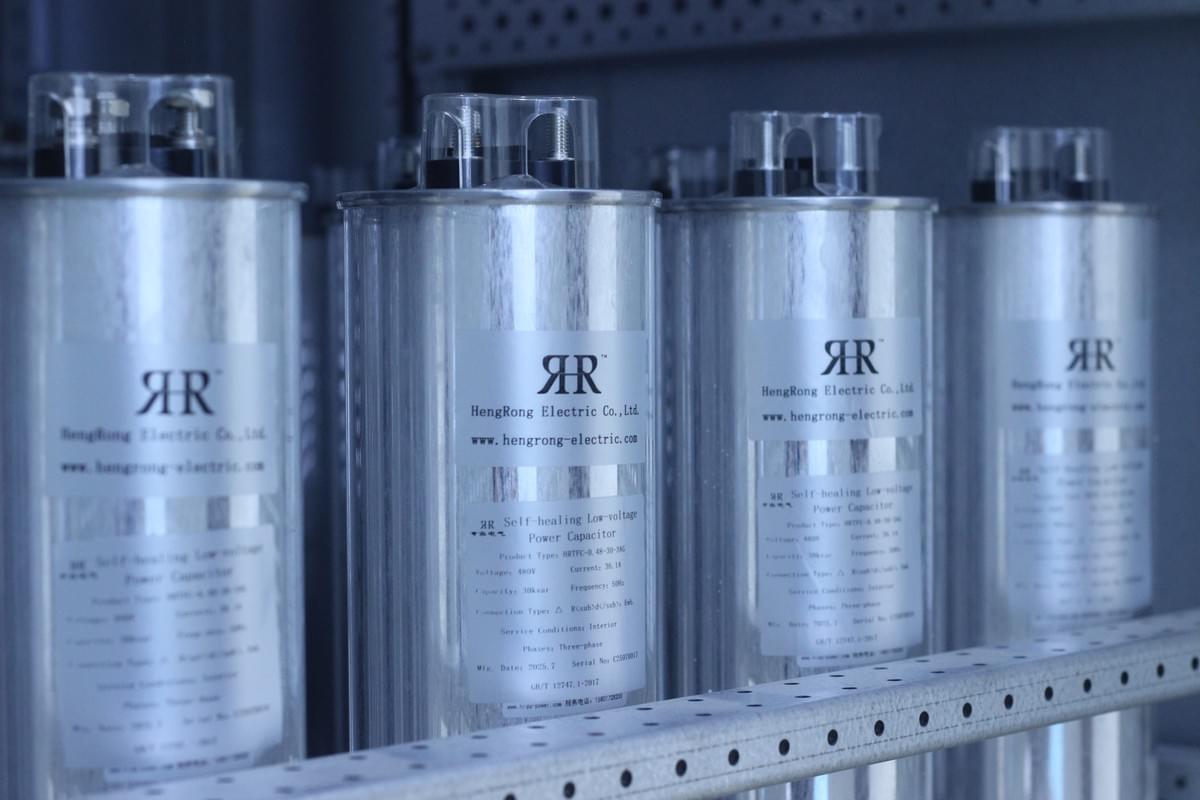
Self-healing Capacitors:
Improve power factor, optimize grid power quality, and extend equipment lifespan with self-healing functionality.
Increased Safety Capacitors:
Designed for hazardous environments with combustible gases, providing high safety and explosion-proof features.
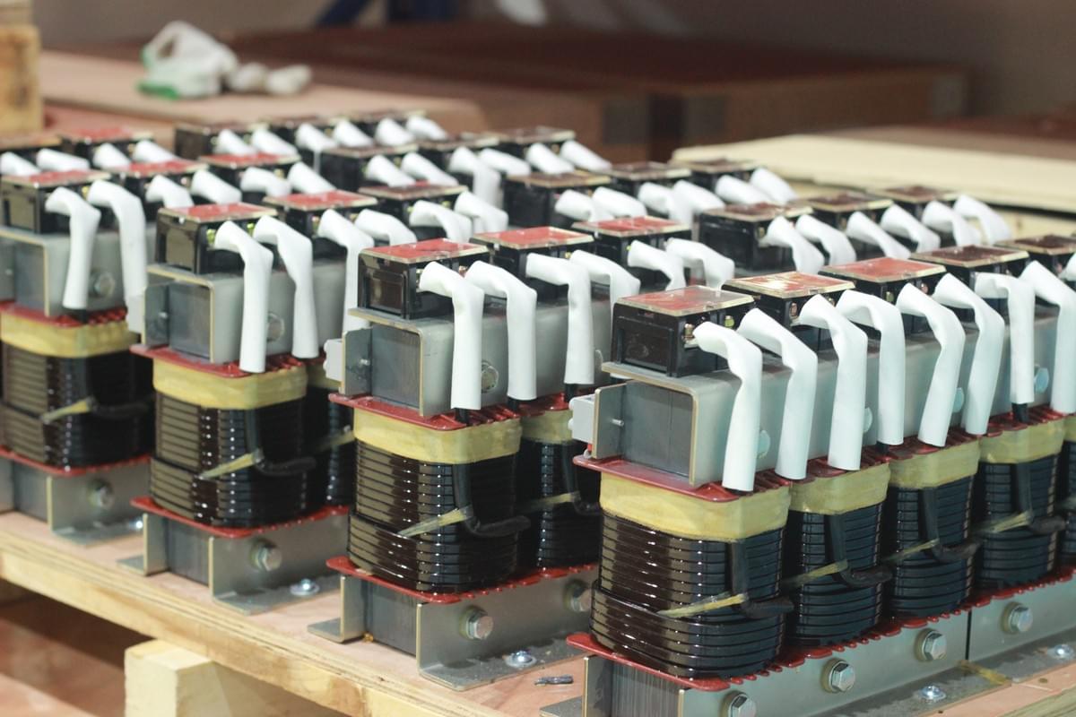
Tuned Reactors:
Effectively absorb grid harmonics, improve voltage waveform stability, and protect capacitors.
Composite and Thyristor Switches: Reliable capacitor switching devices with no inrush current, low noise, and stable operation.
High-voltage Reactive Power Compensation Solutions:
High-voltage Capacitors and Reactors: Enhance high-voltage grid stability, effectively compensate reactive power, and suppress harmonics.
Power Quality Governance:
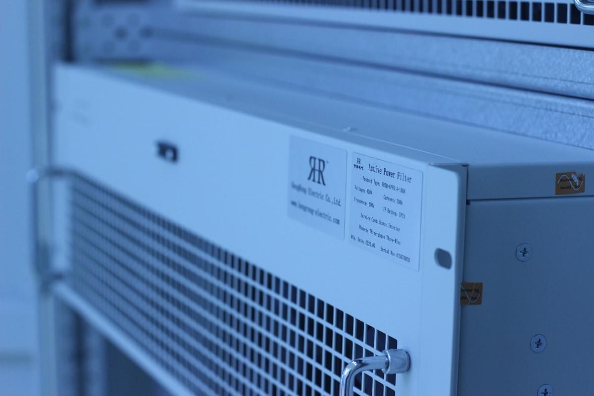
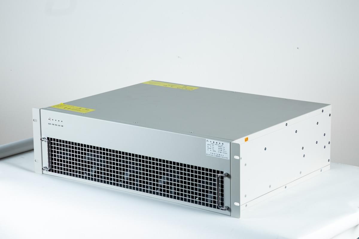
Active Power Filters (APF):
Eliminate harmonics, improve power quality, and ensure system stability.
Static VAR Generators (SVG):
Provide dynamic reactive power compensation with fast and smooth system response.
Smart and Customized Solutions:
Offer smart power quality management controllers and intelligent compensation devices that adapt to complex grid environments, ensuring optimal operation.
Why Choose Hengrong Electric?
Industry Experience: We have extensive experience in power quality optimization, having delivered reliable solutions for numerous clients across various industries.
Customized Services: We provide tailored solutions based on specific client needs, ensuring the maximum benefits for every project.
Technical Assurance: Our products are internationally certified and feature advanced technology, ensuring high efficiency, reliability, and long-term stability.
