
In medical bioelectromagnetic diagnosis, military high-power microwave systems, and industrial precision machining, high-voltage capacitors are critical components—they deliver peak power up to 100MW during discharge. However, practical use requires not just fast charging but precise discharge control to ensure safety and performance. To address this, the high-voltage capacitor charging-discharging parameter tester (integrating real-time monitoring, data collection, and intelligent regulation) has become a key solution for capacitor operation management. This article explains how the tester ensures reliable, efficient capacitor performance through design logic, component selection, and circuit design.

I. Tester Design Logic: A Capacitor-Centric Management System
The tester’s core goal is to intelligently assess and regulate capacitor operation by collecting real-time voltage, current, and other key parameters during charging/discharging. This enhances capacitor stability and safety.
1. Three Core Modules for Full-Cycle Capacitor Regulation
The tester uses a "sensing-control-interaction" architecture, with three modules tailored to capacitor needs:
- Front-end signal acquisition module: High-precision current sensors and high-voltage detectors connect directly to the capacitor’s charging/discharging terminals. They capture real-time current fluctuations and voltage changes, providing raw data for analyzing capacitor status analysis.
- PLC control unit: As the tester’s "brain," it processes signals from the acquisition module, compares measured values against preset capacitor thresholds (e.g., rated voltage, safe current range), and issues precise charging/discharging commands.
- HMI touchscreen: Converts capacitor parameter data into intuitive curves and values for real-time monitoring. It also allows for the manual setting of charging/discharging voltages and durations, enabling human-machine collaboration.
These modules form a "collection-analysis-decision-execution" closed loop, keeping capacitors controllable during charging/discharging and preventing parameter deviations that damage lifespan or safety.
2. Equipment Selection for High-Voltage Capacitor Compatibility
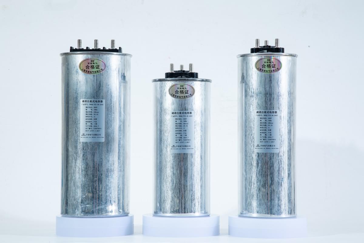
- Capacitor bank configuration: Use "multi-capacitor series-parallel" setups (e.g., 12-parallel-4-series, 8-parallel-2-series) to boost voltage tolerance and total capacitance. Ensure identical capacitor models in one bank; use large-cross-section wires to reduce inductance and avoid oscillation.
- Acquisition sensors: Industrial-grade high-precision current/voltage sensors with ≤±1% error in high-voltage, high-current environments—guaranteeing reliable data for capacitor regulation.
II. Core Component Selection: Customized for Capacitor Management
Component performance defines the tester’s effectiveness. Key components (PLC and touchscreen) are selected to match high-voltage capacitor operating characteristics.
1. PLC: Industrial Integrated Model for Stable Capacitor Control
An industrial integrated PLC is chosen for its compatibility with the capacitor needs:
- Dust and electromagnetic interference resistance (adapts to strong electromagnetic fields from high-voltage capacitors).
- Expandable to 38 analog I/O points, supporting simultaneous regulation of multiple capacitor banks (ideal for large-scale setups).
- Cycle scan response ≤100ms, enabling real-time charging/discharging monitoring to avoid overcharging/overdischarging.
2. Touchscreen: Balanced Capacitor Visibility & Operability
Two industrial touchscreens work in tandem:
- Capacitive HD touchscreen (upper terminal): 4096×4096 resolution displays capacitor charging/discharging curves and parameters. It supports touch-based threshold setting and triggers alarms for abnormalities.
- Surface acoustic wave touchscreen (on-site terminal): 15ms response time, connected to the PLC via RS485—resolving interference in long-distance capacitor parameter transmission.

III. Charging-Discharging Circuit Design: Ensuring Smooth Capacitor Operation
The circuit acts as the bridge between the tester and the capacitor, using closed-loop control split into charging and discharging sections.
1. Closed-Loop Architecture for Precise Capacitor Control
- Charging circuit: Connected to a high-frequency constant-current power supply. The PLC presets charging voltage (e.g., 10kV) and duration; the circuit shuts off automatically when the capacitor reaches the set voltage to prevent overcharging.
- Discharging circuit: The PLC controls the discharge coil on/off, setting the discharge duration (milliseconds/second-level) and frequency. If the current is abnormal, the circuit cuts off immediately to protect the capacitor.
This closed-loop logic ensures charging/discharging meets requirements—balancing energy demands and operational safety.
2. Parameter Optimization for Accurate Capacitor Regulation
Optimize discharge coil inductance (L), resistance (R), and capacitor bank capacitance (C):
- Directly measurable parameters (e.g., coil resistance, capacitor capacitance) have ≤±0.5% error.
- For hard-to-measure parameters (e.g., discharge circuit inductance), derive values using second-order circuit zero-input response principles (capacitor voltage change must balance "capacitor voltage, loop resistance current, and inductor current rate"). Simulate charging/discharging curves to finalize optimal parameters.
For a 1000μF/50A high-voltage capacitor bank, optimizing L=5mH and R=2Ω achieves ±2ms discharge time error and ≤1A current fluctuation—meeting medical field precision needs.
IV. Tester Application Value: Elevating Capacitor Performance
The tester comprehensively improves capacitor management:
- Safety enhancement: Triggers alarms and cuts circuits within 100ms if capacitors overcharge, overdischarge, or have abnormal current—preventing breakdowns and explosions.
- Energy efficiency: Reduces charging/discharging energy consumption by 8% for 10kV/1000μF capacitor banks, saving over 10,000 RMB in annual electricity costs.
- Simplified maintenance: Enables remote monitoring of multiple capacitor banks, automatically stores 1 year of historical data, and cuts maintenance costs by 30%.
In practice:
- Medical equipment: Capacitor discharge energy error ≤±3%.
- Military systems: Charging/discharging response ≤50ms.
- Industrial machining: Improves laser cutting precision by 2-3 grades, lowering scrap rates.
V. Conclusion: Unlocking Capacitor Potential with Innovation
The high-voltage capacitor charging-discharging parameter tester enables full-cycle capacitor management through scientific design. Future integration with IoT will support cluster monitoring of 50+ capacitor banks and mobile APP maintenance—expanding high-voltage capacitor applications in new energy, aerospace, and more.
If your enterprise faces high-voltage capacitor management challenges, share your capacitor model (rated voltage/capacitance) and application scenario. Hengrong Electric Co.,Ltd will deliver a customized solution!