1. Introduction
With the widespread application and development of power electronic technology, a large number of non-linear loads have been added to the power supply system, such as low-voltage small-capacity household appliances, high-voltage large-capacity industrial rectifiers, and frequency converters. Additionally, there are impact and fluctuating loads like arc furnaces, large rolling mills, and electric locomotives. These loads not only cause distortion of grid current and voltage waveforms, leading to harmonic "pollution", but also result in voltage fluctuations, flicker, and three-phase imbalance. This not only endangers the safety of electrical equipment itself but also seriously impairs and interferes with the economical operation of the power grid.

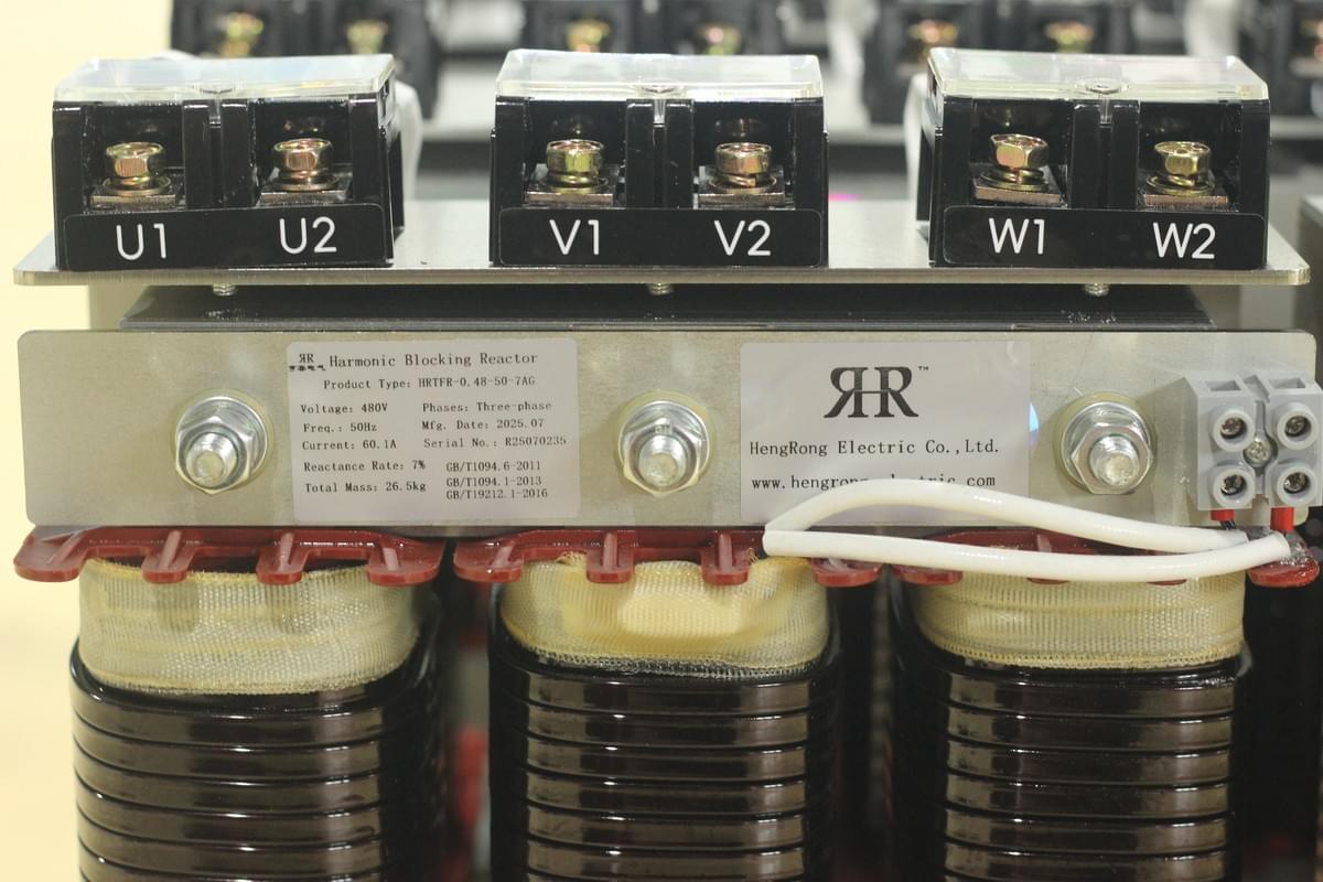
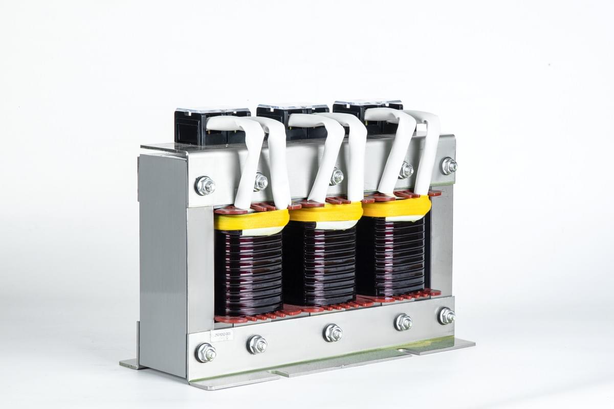
For reactive power compensation equipment, if the harmonic problem at the bus where the shunt capacitor device is connected is not fundamentally addressed, harmonic amplification is likely to occur. Connecting a reactor with an appropriate reactance rate in series in the shunt capacitor circuit is an effective method to solve harmonic amplification and protect capacitors. Its core functions are suppressing high-order harmonics and limiting the inrush current of capacitors during switching-on, while preventing excessive amplification of grid harmonics and harmonic resonance that endangers system safety due to capacitor connection. It should be noted that the selection of the series reactance rate must be based on the background harmonic characteristics of the power grid. The following sections will elaborate on its core functions and the selection of reactance rate.
2. The Role of Series Reactors in Limiting Inrush Current During Switching-On
The reactance rate of the series reactor is a key parameter determining its effect on limiting inrush current, and it should be selected according to the application purpose. Inrush current during switching-on is mainly divided into two types: "inrush current when a single capacitor bank is switched on" and "back-to-back additional inrush current when multiple capacitor banks are switched on". The specific limiting mechanisms and parameter selection are as follows:
(1) Inrush Current When a Single Capacitor Bank is Switched On
- Calculation Model and Formulas
Based on the equivalent circuit for switching on a single capacitor bank (including the equivalent inductance \(L_0\) per phase of the network, the series reactor and wiring inductance \(L\), the capacitance \(C\) per phase, and the circuit breaker QF), the formulas for the maximum inrush current and inrush current frequency are derived:
- Maximum inrush current (peak value): \(I_{max }=\sqrt{2} I_{e}\left(1+\frac{\sqrt{X_{C}}}{\sqrt{X_{L}'}}\right)\)
Where: \(I_{max}\) is the maximum inrush current (kA), \(I_e\) is the rated current of the capacitor bank (kA), \(X_C\) is the capacitive reactance per phase of the capacitor bank (Ω), and \(X_{L}'\) is the combined value of the network inductive reactance and the series inductive reactance (Ω).
- Inrush current frequency: \(f_{y}=f \cdot \frac{\sqrt{X_{C}}}{X_{L}'}\)
Where: \(f_y\) is the inrush current frequency (Hz), and \(f\) is the fundamental frequency of the power grid (Hz).
- Case Analysis
Taking a "100 MVA short-circuit capacity, 10 kV system voltage, 9 Mvar capacitor bank (rated voltage \(11/\sqrt{3}\) kV)" as an example, the inrush current characteristics under different reactance rates are calculated, with the following results:
- The capacitive reactance of the capacitor \(X_C=(11/\sqrt{3})^2/9=4.48\ \Omega\), and the system short-circuit impedance \(X_0=10.5^2/100=1.1025\ \Omega\).
- Inrush current data: Without a series reactor, the inrush current multiple is 4.26 and the inrush current frequency is 100.79 Hz; with a 0.1% reactance rate in series, the inrush current multiple is 4.258 and the frequency is 100.58 Hz; with a 1% reactance rate in series, the inrush current multiple is 4.208 and the frequency is 98.8 Hz; with a 4.5% reactance rate in series, the inrush current multiple is 4.035 and the frequency is 92.67 Hz; with a 6% reactance rate in series, the inrush current multiple is 3.97 and the frequency is 90.37 Hz.
It can be seen that the larger the reactance rate, the slightly lower the inrush current multiple, and the inrush current frequency decreases accordingly. Additionally, the reactance rate should be adjusted based on the length of the circuit wiring (select the upper limit for long wiring and the lower limit for short wiring).

(2) Back-to-Back Additional Inrush Current When Multiple Capacitor Banks Are Switched On
When two or more capacitor banks are connected in parallel to the same bus and some of them are already in operation, switching on an additional bank will generate "back-to-back additional inrush current", which requires a series reactor for suppression (otherwise, it will endanger equipment safety).
- Parameter Selection: A reactor with a reactance rate of 0.1% to 1% or a damped current limiter is usually selected.
- Simplified Calculation: The peak multiple of the additional inrush current during switching-on is \(K_c=\sqrt{2} \cdot \frac{N-1}{N} \cdot \frac{1}{\sqrt{K}}\) (where \(N\) is the total number of capacitor banks and \(K\) is the reactance rate).
- Inrush Current Limit: The inrush current when a single bank is switched on is usually small (when the bus short-circuit capacity is ≤ 80 times the capacitor capacity, the inrush current is ≤ 10 times the rated current peak). When multiple banks are switched on, the inrush current of the last bank is the largest. Based on domestic operation experience, the inrush current peak should be limited to within 20 times the rated current peak, and the fewer the number of groups, the smaller the impact.
- Influence of Circuit Inductance: The current-limiting reactor in the main circuit will increase the circuit inductance. If the inductance of the grouped circuit is large, the inductance of the system current-limiting reactor can be ignored; if there is no reactor or the reactance in the grouped circuit is small, the system inductance must be considered, otherwise, it is easy to cause inaccurate reactance rate. Moreover, the current of the current-limiting reactor will cause an increase in capacitor voltage (which needs to be calculated based on inductance parameters).
3. The Role of Series Reactors in Harmonic Suppression
Grid harmonics threaten the safety of capacitors. Series reactors suppress harmonic amplification and resonance by adjusting the circuit impedance characteristics, with the specific mechanisms as follows:
(1) Circuit Model and Harmonic Current Formulas
Based on the circuit model where the "capacitor device and harmonic source" are connected to the same bus, the key harmonic parameter formulas are derived:
- The nth harmonic current flowing into the capacitor bank: \(I_{cn}=I_{n} \cdot \frac{n X_{s}}{n X_{s}+n X_{L}-X_C/n}\)
- The nth harmonic current flowing into the system: \(I_{sn}=I_{n} \cdot \frac{n X_{L}-X_C/n}{n X_{s}+n X_{L}-X_C/n}\)
- Comprehensive harmonic impedance: \(Z_{n}=\frac{n X_{s}(n X_{L}-X_C/n)}{n X_{s}+(n X_{L}-X_C/n)}\)
- Harmonic current distribution ratio: \(\frac{I_{sn}}{I_n}=\left|\frac{n^2 K-1}{n^2(S+K)-1}\right|\)
Where: \(n\) is the harmonic order, \(X_s\) is the system fundamental equivalent reactance (Ω), \(X_L\) is the series reactor fundamental reactance (Ω), \(X_C\) is the capacitor fundamental capacitive reactance (Ω), \(I_n\) is the nth harmonic current of the harmonic source (A), \(K=X_L/X_C\) (reactance rate), and \(S=X_s/X_C=Q_c/S_d\) (where \(Q_c\) is the capacitor capacity and \(S_d\) is the bus short-circuit capacity).
(2) Resonance Conditions and Avoidance
- Series Resonance: When \(n X_L - X_C/n=0\), series resonance occurs in the capacitor branch, and the resonance order is \(n=1/\sqrt{K}\).
- Parallel Resonance: When \(n X_s + n X_L - X_C/n=0\), parallel resonance occurs between the capacitor and the power grid, and the resonance capacity is \(Q_c=S_d\left(\frac{1}{n^2}-K\right)\).

(3) Case Analysis (100 MVA System + 9 Mvar Capacitor)
The effect of reactors on harmonic suppression/amplification is verified through multiple sets of data, with the core conclusions as follows:
- Without a series reactor (Table 1): The 3rd harmonic is the most significantly amplified (amplification factor of 5.26), the 2nd harmonic is amplified by 1.56 times, and harmonics of the 5th order and above show a suppression trend (0.8 for the 5th order, 0.29 for the 7th order, and 0.10 for the 11th order).
- With different series reactance rates (Tables 2 and 3):
- 4.5% to 7% reactance rate: It can effectively suppress the 5th harmonic (amplification factor of 0.05 at 4.5%), but the 3rd harmonic is still amplified (2.77 times at 4.5% and 0.84 times at 7%);
- 12% reactance rate: It can suppress the 3rd harmonic (amplification factor of 0.09), but the 2nd harmonic is amplified to 3.25 times;
- 1% reactance rate: It severely amplifies the 3rd harmonic (amplification factor of 9.10) and the 5th harmonic by 1.50 times, posing extremely high risks.
- Resonance capacity verification (Table 4):
- 4.5% to 7% reactance rate: The resonance capacity of harmonics of the 5th order and above is negative (no resonance risk), but the 3rd harmonic resonance needs to be verified;
- 1% reactance rate: The resonance capacities of the 5th order (3 Mvar) and 7th order (1.04 Mvar) are positive (resonance risk exists);
- Without a series reactor: All harmonic orders have positive resonance capacities (highest resonance risk).
(4) Influence of System Short-Circuit Capacity
Taking the suppression of the 5th harmonic by a 6% reactance rate as an example, the amplification factor formula \(F=\left|\frac{0.5}{25 Q_c/S_d + 0.5}\right|\) is derived. It can be seen that the larger the system short-circuit capacity, the smaller the suppression effect (larger F value); the smaller the short-circuit capacity, the stronger the suppression effect (smaller F value).
4. Calculation of Steady-State Voltage Rise
After the capacitor is connected to the system, the impact of voltage rise on equipment needs to be calculated. The core formulas and data are as follows:
(1) Bus Voltage Rise
After the capacitor device is connected to the bus, the steady-state voltage rise is calculated as: \(\Delta U \approx U_{ZM} \cdot \frac{Q_c}{S_d}\)
Where: \(\Delta U\) is the voltage rise (kV), \(U_{ZM}\) is the bus voltage before the capacitor is connected (kV), \(Q_c\) is the total capacity of the capacitor (Mvar), and \(S_d\) is the bus short-circuit capacity (MVA).
(2) Capacitor Terminal Voltage Rise
After connecting a series reactor, the capacitor terminal voltage rises due to reactance voltage division, calculated as: \(U_{c}=\frac{U_{M}}{\sqrt{3} S'} \cdot \frac{1}{1-K}\)
Where: \(U_c\) is the capacitor terminal voltage (kV), \(U_M\) is the bus voltage (kV), \(S'\) is the number of series sections of capacitors per phase, and \(K\) is the reactance rate.
(3) Voltage Selection for 10 kV Systems (Table 5)
Capacitor rated voltages and reactor terminal voltages corresponding to different reactance rates:
- 1% reactance rate: Select a capacitor with a rated voltage of \(10.5/\sqrt{3}\) kV, and the reactor terminal voltage is 0.06 kV;
- 4.5% to 7% reactance rate: Select a capacitor with a rated voltage of \(11/\sqrt{3}\) kV, and the terminal voltage is 0.286 to 0.445 kV;
- 12% to 13% reactance rate: Select a capacitor with a rated voltage of \(12/\sqrt{3}\) kV, and the terminal voltage is 0.831 to 0.901 kV.

5. General Principles for Selecting the Reactance Rate of Reactors
The selection of reactance rate must focus on the two core goals of "harmonic suppression" and "inrush current limitation", and be determined based on the background harmonic characteristics of the power grid:
- For limiting inrush current during switching-on only: Select a reactance rate of 0.1% to 1% (no need to consider harmonic suppression).
- When the background harmonic is of the 5th order or above: Select a reactance rate of 4.5% to 6% (focus on suppressing the 5th harmonic and avoiding resonance).
- When the background harmonic is of the 3rd order or above: Prioritize a reactance rate of 12%; alternatively, a combination of 4.5% to 6% and 12% reactance rates can be used, but it is necessary to verify whether the 3rd harmonic amplification meets the national standard (GB/T 14549-1993).
- Risk Avoidance:
- For a reactance rate of 0.1% to 1%: Prevent amplification or resonance of the 5th and 7th harmonics;
- For a reactance rate of 4.5% to 6%: Prevent amplification or resonance of the 3rd harmonic.
6. Recommendations for Selecting Series Reactors
- New Substations: Reactors and capacitors cannot be randomly combined. It is necessary to calculate the harmonic background at the connection point and the system short-circuit capacity in advance to ensure parameter matching.
- Commissioned Devices: The rationality of the reactance rate must be confirmed through verification and on-site measurement. For devices with a reasonable reactance rate, the capacitor capacity must not be increased or decreased arbitrarily; for devices with an unreasonable reactance rate, the matching reactor must be replaced.
- Comprehensive Governance Principle: Series reactors are only a "symptomatic" measure. Grid harmonic governance must follow the systematic principles of "who pollutes, who governs" and "multi-level governance and hierarchical coordination" to control harmonic generation from the source (e.g., optimizing the design of non-linear loads).
7. References
References
:
- [1] GB/T 14549-1993 Power Quality - Harmonics in Public Power Grids [S]
- [2] GB 50227-1995 Code for Design of Shunt Capacitor Installations [S]
[3] Yang Changxing. Harmonic Response of Shunt Capacitor Installations and Its Suppression Measures [J]. Zhejiang Electric Power, 1994(1)(2)
Hengrong Electric Co., Ltd.
We specialize in providing high-efficiency reactive power compensation and power quality optimization solutions. With over 20 years of industry experience, our products excel in enhancing grid efficiency, reducing energy consumption, and ensuring system stability.
Our core products and services include:
Low-voltage Reactive Power Compensation and Power Quality Optimization:
Self-healing Capacitors:
Improve power factor, optimize grid power quality, and extend equipment lifespan with self-healing functionality.
Increased Safety Capacitors:
Designed for hazardous environments with combustible gases, providing high safety and explosion-proof features.
Tuned Reactors:
Effectively absorb grid harmonics, improve voltage waveform stability, and protect capacitors.
Composite and Thyristor Switches: Reliable capacitor switching devices with no inrush current, low noise, and stable operation.
High-voltage Reactive Power Compensation Solutions:
High-voltage Capacitors and Reactors: Enhance high-voltage grid stability, effectively compensate reactive power, and suppress harmonics.
Power Quality Governance:
Active Power Filters (APF):
Eliminate harmonics, improve power quality, and ensure system stability.
Static VAR Generators (SVG):
Provide dynamic reactive power compensation with fast and smooth system response.
Smart and Customized Solutions:
Offer smart power quality management controllers and intelligent compensation devices that adapt to complex grid environments, ensuring optimal operation.
Why Choose Hengrong Electric?
Industry Experience: We have extensive experience in power quality optimization, having delivered reliable solutions for numerous clients across various industries.
Customized Services: We provide tailored solutions based on specific client needs, ensuring the maximum benefits for every project.
Technical Assurance: Our products are internationally certified and feature advanced technology, ensuring high efficiency, reliability, and long-term stability.
