I. Introduction
In the process of electricity generation and transmission, the generation of harmonics is a problem that cannot be ignored. Harmonics not only reduce the efficiency of electricity usage and transmission, but also cause overheating of electrical system equipment, accelerate the aging of line insulation, and seriously affect the service life of equipment. More seriously, harmonics may cause series resonance or parallel resonance, instantly damage electrical components and equipment, and even interfere with relay protectors and automatic control devices, resulting in metering confusion and misoperation. To solve the harmonic problem in the 400V system of Wenchang 9-2/9-3 Central Platform, relevant researchers have carried out in-depth analysis and research. Through the analysis of harmonic sources, harmonic calculation, and finally selecting active filters for treatment, the calculation process and selection principles can provide important references for similar projects.

II. System Working Conditions and Parameter Description
(I) Distribution of Grid Harmonic Sources
In the equipment configuration of Wenchang 9-2/9-3 Platform, there are 5 devices driven by low-voltage frequency converters, which are the main harmonic sources in the system. These include 2 low-voltage screw compressors (2×220kW) distributed in CEP-LOV-001 LA section (CEP-C-2809/2810), and 3 external transfer pumps (3×45kW) distributed in CEP-LOV-001 LA (2001A/B), CEP-P-2001A/B/C, and LB (2001C) sections respectively.
(II) System Working Conditions
Under normal load conditions, the main power station of Wenchang 9-2/9-3 Platform supplies power to all module electrical loads. In this working condition, the LA section bus is powered through ACB103 or ACB101. During the peak period of electrical load from 2021 to 2023, due to the possible insufficient power supply capacity of the main power station, it is necessary to use the power station on the drilling module for reverse power supply. During the reverse power supply period, the drilling module and the module do not operate in parallel. Therefore, according to the design principle of reverse power supply, the LA bus section will be disconnected from the platform module power grid, and the LA section will be separately powered by the platform drilling module power grid through ACB108.
(III) System Parameters
The main technical conditions and parameters of the 400V low-voltage system are as follows:
- CEP-LOV-001-LA system: minimum short-circuit current is 32.298kA (1.1s, approximate steady-state short-circuit current).
- CEP-LOV-001-LB system: minimum short-circuit current is 30.752kA (1.1s, approximate steady-state short-circuit current).
- Grounding mode of 400V low-voltage distribution system: neutral point insulated system.

III. Theories and Calculations Related to Grid Harmonics
(I) Definition of Harmonics
Harmonics refer to the distortion of voltage and current waveforms. Generally, they are explained as a series of sinusoidal components with periodic frequencies greater than the fundamental frequency of the power grid, and the frequency is generally an integer multiple of the fundamental frequency of the power grid. Due to their nonlinear characteristics, all harmonics are generated by harmonic sources. Harmonic sources initially only generate harmonic currents. Due to current distortion transmission, corresponding harmonic voltage drops are formed on lines and transmission equipment, generating local voltages, which will cause distortion of the original sinusoidal voltage and serious consequences of disordered waveform of electric energy transmitted by the power grid.
(II) Grid Harmonic Calculation Methods
Harmonics generated by power transmission generally have symmetry, independence, and phase sequence. The power system grid has relatively independent responses to harmonics of different orders. Therefore, harmonics of each order can be processed separately, separate equivalent circuits can be established for harmonics of each order, and then harmonic currents and harmonic voltages of each order can be calculated. The total harmonic response value is obtained by summing all harmonic components.
- Indicators of harmonic waveform distortion
- Harmonic Ratio (HR): The ratio of the root-mean-square value of the k-th harmonic component of the periodic transmission AC quantity to the root-mean-square value of the fundamental component, expressed as a percentage.
- Total Harmonic Distortion (THD): The ratio of the root-mean-square value of the total periodic harmonic components of the transmission AC quantity to the root-mean-square value of the fundamental component, expressed as a percentage.
- Harmonic current calculation formulas
- Harmonic Current Ratio (HRI) of the h-th harmonic: HRIₕ = (Iₕ / I₁) × 100%, where Iₕ is the root-mean-square value of the h-th harmonic current (A), and I₁ is the root-mean-square value of the fundamental current (A).
- Harmonic current content (Iₕ): Iₕ = √[∑(Iₕ)²] (h from 2 to ∞).
- Superposition of harmonic currents of the same order from two harmonic sources on the same line: calculated according to the known phase angle: Iₕ = √[Iₕ₁² + Iₕ₂² + 2Iₕ₁×Iₕ₂×cosθₕ], where Iₕ₁ is the h-th harmonic current from harmonic source 1 (A), Iₕ₂ is the h-th harmonic current from harmonic source 2 (A), and θₕ is the phase angle between the h-th harmonic currents from harmonic source 1 and harmonic source 2 (°).
- If the phase angle is uncertain, it can be calculated as follows: Iₕ = √[Iₕ₁² + Iₕ₂² + Kₕ×Iₕ₁×Iₕ₂], where the coefficient Kₕ is selected according to Table 1.
- For the superposition of more than two harmonic currents of the same order, first superimpose the harmonic currents of two orders, then continue to superimpose the harmonic current of the third order, and so on to superimpose all harmonic currents.
- Harmonic voltage calculation formulas
- Harmonic Voltage Ratio (HRU) of the h-th harmonic: HRUₕ = (Uₕ / U₁) × 100%, where Uₕ is the root-mean-square value of the h-th harmonic voltage (V), and U₁ is the root-mean-square value of the fundamental voltage (V).
- Harmonic voltage content (Uₕ): Uₕ = √[∑(Uₕ)²] (h from 2 to ∞).
- Total harmonic distortion rate of voltage (THDᵤ): THDᵤ = (Uₕ / U₁) × 100%.

(III) Calculation of Harmonic Source Current
Harmonic current calculation is based on bus sections: CEP-LOV-001-LA (Table 2); bus section: CEP-LOV-001-LB (Table 3).
- CEP-LOV-001-LA section harmonic current data: For a load power of 45kW, the 19th, 17th, and 13th harmonic currents are all 1.96A, the 11th is 2.62A, the 7th is 11.03A, and the 5th is 25.99A; for a load power of 220kW, the 19th, 17th, and 13th harmonic currents are all 9.54A, the 11th is 12.71A, the 7th is 53.97A, and the 5th is 127.04A; the total harmonic current is 281.06A.
- CEP-LOV-001-LB section harmonic current data: For a load power of 45kW, the 19th, 17th, and 13th harmonic currents are all 1.96A, the 11th is 2.62A, the 7th is 11.03A, and the 5th is 25.99A; the total harmonic current is 28.69A.
(IV) Judgment Conditions
GB/T 14549—1993 "Power Quality - Harmonics in Public Supply Networks" stipulates the requirements for power quality. The standard specifies that in 380V power grids, the allowable limit of harmonic voltage ratio for each odd harmonic is 4%, and for each even harmonic is 2%. The allowable value of total harmonic voltage distortion rate (THD) is 5%, all referring to phase voltage. It also specifies the allowable value of harmonic current injected into the public connection point of the power grid. Under the conditions of standard voltage 380V and reference short-circuit capacity 10000kV·A, the allowable value of harmonic current injected into the public connection point is shown in Table 4.
Since the short-circuit capacity at the Point of Common Coupling (PCC) is different from the assumed reference minimum short-circuit capacity, conversion shall be carried out in accordance with Appendix B of GB/T 14549—1993. The conversion formula is: Iₕ = (Sₖ₁ / Sₖ₂) × Iₕ₁, where Sₖ₁ is the minimum short-circuit capacity at the public connection point (kV·A), Sₖ₂ is the reference short-circuit capacity (kV·A), and Iₕ₁ is the allowable value of the h-th harmonic current in Table 2 (A).
After conversion, the allowable values of harmonic currents in the 400V system LA and LB sections of Wenchang are as follows:
- LB section: short-circuit capacity 21.30MV·A, correction factor 2.13, allowable 5th harmonic current 132.09A, 7th 93.74A, 11th 59.65A, 13th 51.13A, 17th 38.35A, 19th 34.09A, 23rd 29.83A, 25th 25.57A.
- LA section: short-circuit capacity 22.38MV·A, correction factor 2.238, allowable 5th harmonic current 138.73A, 7th 98.45A, 11th 62.65A, 13th 53.70A, 17th 40.28A, 19th 35.80A, 23rd 31.33A, 25th 26.85A.
After calculation, the 5th harmonic current in the LA section exceeds the standard by 122.70A, while the harmonic current in the LB section does not exceed the standard.
IV. Selection of Active Power Filter
(I) Design Requirements
After harmonic treatment of the low-voltage public power grid using active power filters, the public power grid must meet the following two conditions: ① Take the minimum allowable value of grid harmonic current as the harmonic current injected into the public point of the low-voltage grid; ② Ensure that the total harmonic distortion rate of the grid voltage is less than 5%, and the harmonic voltage ratio of each odd order is less than 4%.
(II) System Configuration
Considering that Wenchang 9-2/9-3 Central Platform is an independent power supply and distribution system with its own power source (belonging to a weak power grid), and the harmonic content of the system cannot be accurately measured before project design, selection, and commissioning, in order to ensure the integrity and rationality of the system design, combined with the power consumption conditions of similar engineering projects, harmonics in Wenchang 9-2/9-3 Central Platform are treated by configuring active power filters, with a design margin of 10%~15% reserved.
Harmonic currents of each section after increasing the design margin:
- Complete filtering for CEP-LOV-001 LA section: 281.06A × 110% ≈ 310A.
- Since the proportion of harmonic content in CEP-LOV-001 LB section is very small, no filtering device needs to be configured.
(III) Configuration Effect
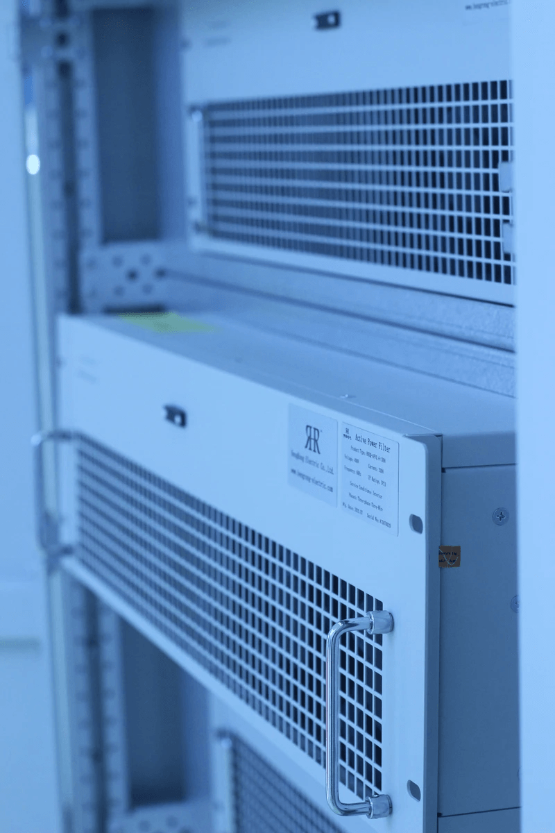
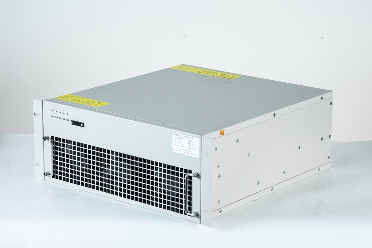
Based on the calculated harmonic current value of the LA section, an active power filter with a capacity of 310A is selected. Table 7 shows the harmonic current and harmonic voltage conditions after configuring the 310A active power filter. After configuration, the harmonic currents and voltages of the 5th, 7th, 11th, 13th, 17th, 19th, 23rd, and 25th orders in the LA section are all reduced to within the allowable range, meeting the design requirements, effectively treating the harmonic problem, and providing a guarantee for the reliable operation of the platform.
V. Conclusion
The 400V system of Wenchang 9-2/9-3 Central Platform has harmonic problems generated by equipment driven by low-voltage frequency converters. Through the analysis of system harmonic sources, harmonic calculation, and judgment based on relevant national standards, it is clear that the 5th harmonic current in the LA section exceeds the standard. To address this situation, an active power filter with a capacity of 310A is selected for harmonic treatment in the LA section, with a design margin of 10%~15% reserved, while no configuration is needed in the LB section due to its low harmonic content. After configuration, the system harmonic current and voltage meet the standard requirements, effectively solving the harmonic problem. The calculation process and selection principles have a universal application basis and can provide important references for harmonic calculation and active power filter selection in similar construction projects, ensuring the stable and efficient operation of power systems in similar projects.

Through the systematic analysis of harmonic problems and the design of treatment schemes for Wenchang Central Platform, it fully reflects the importance of scientific analysis, accurate calculation, and reasonable selection of equipment for harmonic problems in industrial power systems, providing practical experience for ensuring the safe and stable operation of power systems. In future similar projects, this method can be used for reference, and combined with the specific characteristics of the project, better harmonic treatment schemes can be formulated to further improve the operation quality and efficiency of power systems.
Hengrong Electric Co., Ltd.
We specialize in providing high-efficiency reactive power compensation and power quality optimization solutions. With over 20 years of industry experience, our products excel in enhancing grid efficiency, reducing energy consumption, and ensuring system stability.
Our core products and services include:
Low-voltage Reactive Power Compensation and Power Quality Optimization:
Self-healing Capacitors:
Improve power factor, optimize grid power quality, and extend equipment lifespan with self-healing functionality.
Increased Safety Capacitors:
Designed for hazardous environments with combustible gases, providing high safety and explosion-proof features.
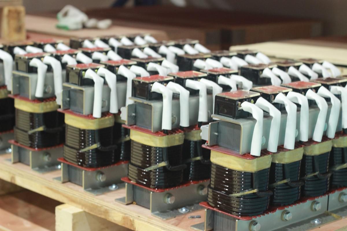
Tuned Reactors:
Effectively absorb grid harmonics, improve voltage waveform stability, and protect capacitors.
Composite and Thyristor Switches: Reliable capacitor switching devices with no inrush current, low noise, and stable operation.
High-voltage Reactive Power Compensation Solutions:
High-voltage Capacitors and Reactors: Enhance high-voltage grid stability, effectively compensate reactive power, and suppress harmonics.
Power Quality Governance:
Active Power Filters (APF):
Eliminate harmonics, improve power quality, and ensure system stability.
Static VAR Generators (SVG):
Provide dynamic reactive power compensation with fast and smooth system response.
Smart and Customized Solutions:
Offer smart power quality management controllers and intelligent compensation devices that adapt to complex grid environments, ensuring optimal operation.
Why Choose Hengrong Electric?
Industry Experience: We have extensive experience in power quality optimization, having delivered reliable solutions for numerous clients across various industries.
Customized Services: We provide tailored solutions based on specific client needs, ensuring the maximum benefits for every project.
Technical Assurance: Our products are internationally certified and feature advanced technology, ensuring high efficiency, reliability, and long-term stability.
