
In the reactive power compensation system of 35kV power grids, capacitor banks are crucial equipment for enhancing power factor and stabilising bus voltage. However, the safe operation of capacitors is highly dependent on the reasonable configuration of series reactors. Improper selection of reactor reactance rate can lead to harmonic amplification in capacitor banks, excessive inrush current during switching, and even abnormal noise and equipment damage. Based on an engineering case of a capacitor bank on the 35kV side of a 220kV substation in East China, this article details the selection logic, abnormal analysis, and adjustable optimisation solutions for series reactors in capacitor banks, providing technical support for the safe and efficient operation of power grids.
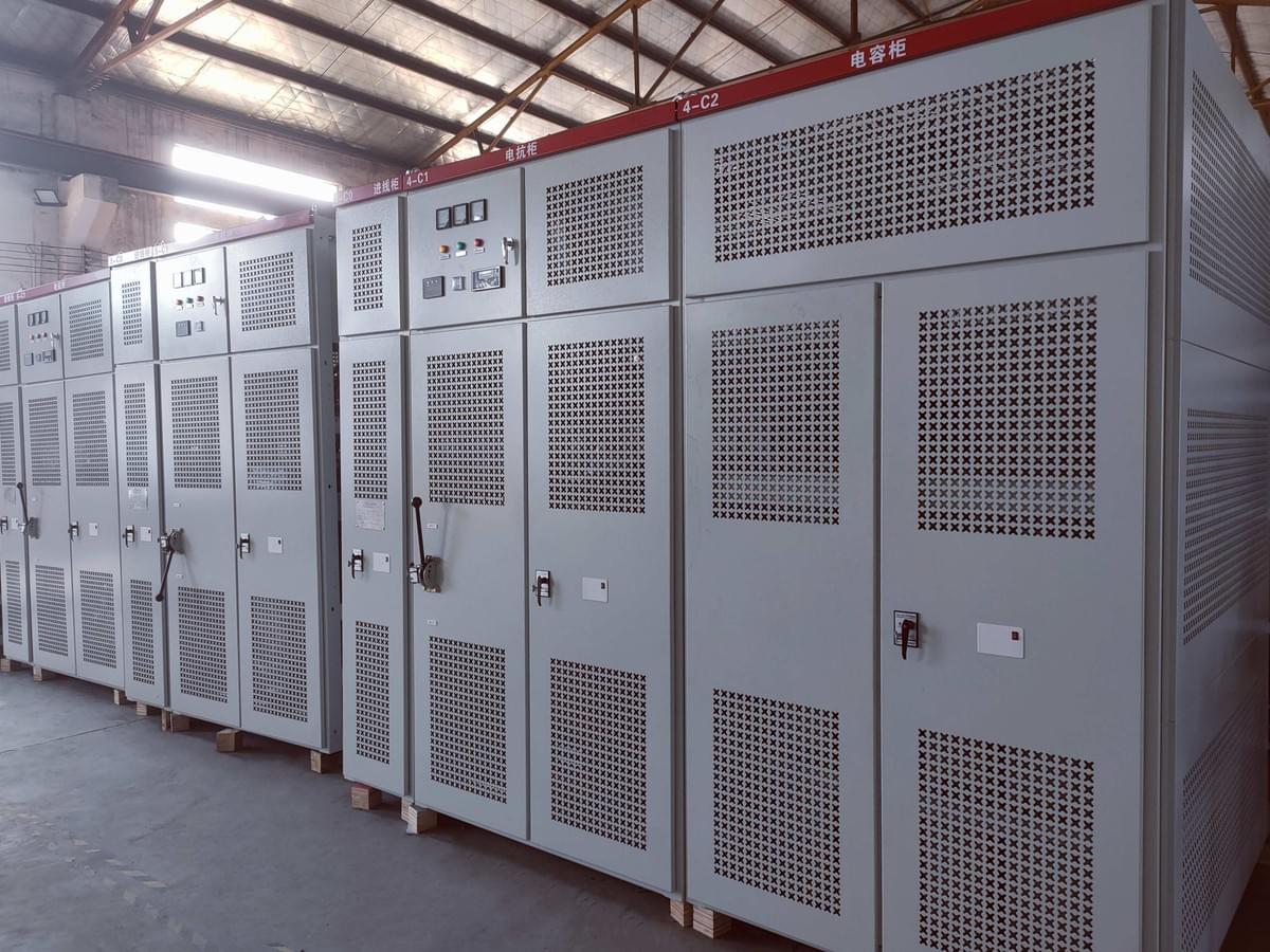
I. Capacitors and Reactors: The "Golden Pair" for Reactive Power Compensation in 35kV Grids
Capacitor banks inject capacitive reactive power to increase the power grid’s power factor from 0.7-0.8 to above 0.95, which not only reduces line losses by 10%-15% but also avoids electricity fines imposed by power supply companies for low power factor (usually 0.5%-1% of the total electricity fee). However, capacitors operating alone face two major pain points that severely restrict their service life and operational efficiency:
1. Risk of Harmonic Amplification Threatens Capacitor Safety
Nonlinear loads (such as frequency converters, rectifiers, and arc furnaces) in modern industrial power grids generate significant 3rd, 5th, 7th, and other odd harmonics. Capacitors themselves exhibit capacitive impedance, and when connected directly to the grid without series reactors or with improperly selected reactance rates, they can form parallel resonance with the inherent inductance of the power grid (such as transformer leakage inductance and line inductance). This resonance phenomenon causes the harmonic current to be amplified several times, resulting in overvoltage and overcurrent across the capacitors. In the case of a 220kV substation in Jiangsu Province, after configuring a series reactor with a 3.43% reactance rate for the 10MVar capacitor bank on the 35kV side, the total harmonic distortion (THD) of the bus voltage reached 4.42%, exceeding the State Grid’s limit of 4%. The 3rd harmonic distortion rate was as high as 3.56%, exceeding the 3.2% limit specified in GB/T 14549-1993, which seriously accelerated the insulation aging of capacitors and increased the risk of internal breakdown.
2. Inrush Current Impact Shortens Capacitor Lifespan
When capacitor banks are switched on, they are equivalent to a sudden short circuit of a capacitive load, generating a huge inrush current. Without series reactors, the peak inrush current can reach 30-50 times the rated current of the capacitor bank, which can easily break down the internal dielectric insulation of the capacitors and damage the switching equipment. Series reactors limit the rate of current rise through their inductive characteristics, thereby suppressing inrush current. However, if the reactance rate is too low (less than 2%), the inrush current suppression effect is unsatisfactory; if the reactance rate is too high (more than 10%), it will significantly reduce the reactive power output of the capacitor bank, affecting the reactive power compensation efficiency. In the aforementioned substation case, the reactor with a 3.43% reactance rate could not effectively suppress the inrush current during the sequential switching of two 5MVar capacitor banks, with the peak inrush current reaching 8 times the rated current, posing a serious impact risk to the capacitor bank and circuit breaker.
3. Precise Reactor Matching Unlocks Full Capacitor Performance
Reasonably selected series reactors can achieve a balance between harmonic suppression, inrush current limitation, and reactive power compensation efficiency, fully releasing the performance potential of capacitor banks. Engineering data shows that reactors with appropriate reactance rates can control the peak inrush current of capacitor banks to within 5 times the rated current, meet the inrush current limit requirements of switching equipment, and reduce the total harmonic distortion rate of the grid to below 4%. This ensures that capacitor banks operate under safe voltage and current conditions, maximizing their reactive power compensation effect while extending their service life by 3-5 years.
II. Reactor Selection for Capacitor Banks: Core Calculation Logic in 35kV Grids
The core of selecting series reactors for capacitor banks is determining the optimal reactance rate, which must comprehensively balance three core goals: harmonic suppression, inrush current limitation, and resonance avoidance. The selection process requires combining the grid harmonic background, load characteristics, and capacitor bank parameters for precise calculation.
1. Foundation of Reactance Rate Selection: Resonance Avoidance is a Prerequisite
After capacitor banks are connected in series with reactors, the series combination forms a resonant circuit. To avoid resonance with major harmonics in the grid, the reactance rate must be reasonably selected based on the harmonic order. The core principle is derived from the series resonance condition: when the inductive reactance of the reactor is equal to the capacitive reactance of the capacitor bank at a certain harmonic frequency, series resonance occurs. To avoid this, the reactance rate K must satisfy K > 1/n² (where n is the harmonic order):
- For the 3rd harmonic (n=3), the critical reactance rate is 1/3² ≈ 11.1%, so K > 11.1% is required to avoid resonance with the 3rd harmonic;
- For the 5th harmonic (n=5), the critical reactance rate is 1/5² = 4%, so K > 4% is required to avoid resonance with the 5th harmonic;
- For the 7th harmonic (n=7), the critical reactance rate is 1/7² ≈ 2.04%, so K > 2.04% is required to avoid resonance with the 7th harmonic.
In the aforementioned substation case, the selected 3.43% reactance rate was less than 4%, which failed to avoid resonance with the 5th harmonic in the grid, leading to parallel resonance between the capacitor bank and the 5th harmonic and significant harmonic amplification.
2. Harmonic Suppression: Matching Reactance Rate to Load Characteristics
The selection of the reactance rate must be tailored to the harmonic background of the grid and the type of user-side loads. Different load scenarios require corresponding reactance rate configurations:
- Scenarios with significant 3rd harmonics (e.g., arc furnaces, fluorescent lighting loads): A reactance rate of 12% or higher must be used. This reactance rate is much higher than the critical resonance point of the 3rd harmonic, effectively suppressing the amplification of 3rd harmonic current and avoiding capacitor overheating and insulation damage;
- Scenarios with dominant 5th and 7th harmonics (e.g., frequency converters, rectifier loads): A 7% reactance rate is the optimal choice. This reactance rate is far from the resonance points of the 5th and 7th harmonics, achieving effective harmonic suppression while minimizing the impact on the reactive power compensation efficiency of capacitors;
- Scenarios without high-order harmonics (e.g., pure resistive and inductive loads such as motors): A 2%-3% reactance rate can be used. This low reactance rate can meet the inrush current suppression requirement while maximizing the reactive power output of the capacitor bank.
3. Inrush Current Limitation: Ensuring Safe Switching
The peak inrush current during capacitor bank switching is a key indicator affecting equipment safety. According to the "Technical Guidelines for Reactive Power Compensation Equipment in Power Grids", the per-unit value of the peak inrush current during capacitor bank switching should not exceed 5. The reactance rate must be selected to meet this requirement:
- The calculation formula for inrush current suppression shows that a reactance rate of 5%-9% can effectively control the peak inrush current to within 4-5 times the rated current, achieving the best balance between suppression effect and compensation efficiency;
- For capacitor banks with large capacity (above 10MVar) or frequent switching requirements, a slightly higher reactance rate (7%-9%) is recommended to further reduce the impact of inrush current on capacitors and switching equipment.
4. Case Verification: Hazards of Incorrect Selection
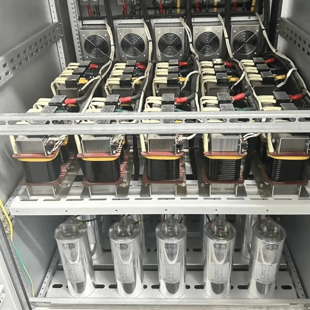
After configuring a series reactor with a 3.43% reactance rate for the 10MVar capacitor bank (24 capacitors of 457kVar each, connected in 4-series and 2-parallel) on the 35kV side of a 220kV substation:
- Harmonic overrun: The total bus harmonic distortion rate was 4.42% (exceeding the limit by 0.42%), and the 3rd harmonic distortion rate was 3.56% (exceeding the limit by 0.36%), leading to overvoltage across the capacitors;
- Inrush current problem: During the switching of two additional 5MVar capacitor banks, the peak inrush current reached 8 times the rated current, causing obvious vibration and abnormal noise of the capacitor bank;
- Equipment risk: After 6 months of operation, partial discharge detection found that the insulation level of 3 capacitors decreased by 20%, and the capacitance deviation exceeded ±5%, requiring urgent replacement to avoid cascading failures.
III. Optimization Solution for Capacitor Banks: Innovative Application of Adjustable Reactors
Traditional fixed-reactance-rate reactors have fixed parameters and cannot adapt to dynamic changes in grid load and harmonic conditions. For example, when the proportion of nonlinear loads increases, the harmonic content of the grid rises, and the original reactance rate may no longer meet the harmonic suppression requirement; when the load is light, the low harmonic content makes the high reactance rate unnecessary and reduces the compensation efficiency. Adjustable reactors, with their flexible reactance rate adjustment function, have become the ideal matching equipment for modern capacitor banks.
1. Core Advantages of Adjustable Reactors
Adjustable reactors adopt a controllable inductance structure, with a reactance rate adjustment range of 0%-12%, which can be adjusted in real-time according to the operating conditions of the capacitor bank and grid parameters:
- Switching phase: Adjust the reactance rate to 5%-9% to strongly suppress the inrush current during capacitor bank switching, avoiding overvoltage impact on the capacitors and ensuring the safe operation of the circuit breaker;
- Stable operation (no high-order harmonics): Adjust the reactance rate to 0 to maximize the reactive power compensation effect of the capacitor bank, minimizing reactive power loss and improving economic efficiency;
- Excessive 3rd harmonics: Adjust the reactance rate to 12% to accurately suppress the amplification of 3rd harmonic current, reducing the harmonic distortion rate to within the standard limit;
- Excessive 5th and higher harmonics: Adjust the reactance rate to 7% to balance harmonic suppression and operational efficiency, ensuring both capacitor safety and compensation effect;
- Shutdown phase: Adjust the reactance rate to 4%-6% in advance to suppress restrike overcurrent caused by circuit breaker opening and reduce the recovery voltage at the capacitor ports, avoiding insulation breakdown.

2. Performance Improvement After Optimization
After replacing the fixed-reactance-rate reactor with an adjustable model for the problematic capacitor bank in the 220kV substation, the operational effect was significantly improved after 1 year of commissioning:
- Harmonic distortion rate: The total harmonic distortion rate of the bus voltage decreased from 4.42% to 3.8%, and the 3rd harmonic distortion rate decreased from 3.56% to 2.9%, both fully meeting the State Grid’s operation limits;
- Inrush current control: The peak inrush current during capacitor bank switching was reduced to below 4 times the rated current, reducing the risk of impact damage to capacitors by 80% and extending the service life of the circuit breaker by 5 years;
- Operational flexibility: The adjustable reactor can automatically adjust the reactance rate according to the grid harmonic and load changes (with an adjustment response time of less than 50ms), adapting to different operating conditions such as peak load, light load, and load switching. The annual failure rate of the capacitor bank decreased from 3.2% to 0.5%;
- Economic benefit: The optimized capacitor bank operates more efficiently, reducing the substation’s annual line loss by 280,000 kWh and avoiding potential equipment replacement costs of over 500,000 yuan.
3. Key Engineering Adaptation Points for Adjustable Reactors
To ensure the reliable operation of adjustable reactors and their optimal matching with capacitor banks, the following key points must be considered during engineering application:
- Capacity matching: The rated capacity of the adjustable reactor must be consistent with the total capacity of the capacitor bank (e.g., a 10MVar capacitor bank is matched with a 10MVar adjustable reactor) to avoid overload during full-load operation;
- Adjustment accuracy: The reactance rate adjustment step should not exceed 1% to ensure the precision of harmonic suppression and inrush current control, avoiding excessive adjustment that affects system stability;
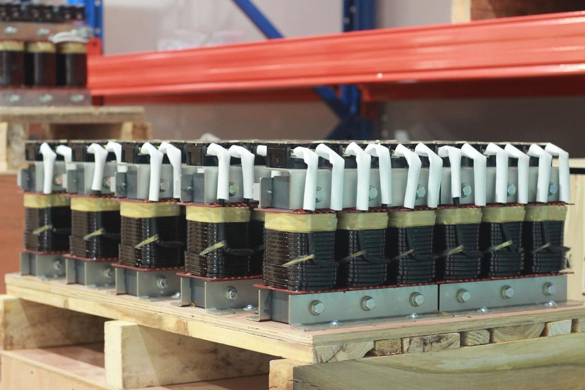
- Reliability design: Adopt a dry-type air-core structure, which has the advantages of moisture-proof, dust-proof, anti-aging, and low noise, adapting to the outdoor harsh operating environment of substations;
- Control system: Equipped with an intelligent control module that can real-time collect grid harmonic data, capacitor bank operating parameters (voltage, current, temperature), and automatically adjust the reactance rate through algorithm calculation, realizing unattended operation.
IV. Key Considerations for Reactor Selection and Operation of Capacitor Banks
1. Three Essential Tasks Before Selection
- Comprehensive harmonic detection: Use professional harmonic analyzers to conduct 24-hour continuous monitoring of the grid, clarify the content, frequency, and variation law of major harmonics (3rd, 5th, 7th, etc.), and provide a basis for reactance rate selection;
- Detailed load analysis: Evaluate the type, proportion, and operating characteristics of user-side nonlinear loads, determine the priority of harmonic suppression, and judge whether the load is stable or fluctuating (fluctuating loads require adjustable reactors);
- Accurate parameter calculation: Based on the grid short-circuit capacity, capacitor bank capacity, and harmonic detection results, use professional calculation software (such as ETAP, PSCAD) to simulate and calculate the optimal reactance rate, avoiding experience-based selection that leads to mismatching.
2. Core Operation and Maintenance Points
- Regular monitoring: Install online monitoring devices for capacitor banks and reactors, monitor operating parameters such as capacitor voltage, current, temperature, and harmonic distortion rate quarterly, and adjust the reactance rate promptly if abnormalities are found;
- Prohibition of arbitrary modifications: For capacitor banks with matched reactors, do not arbitrarily increase or decrease the number of capacitors, replace capacitors of different capacities, or change the wiring method, as this will destroy the impedance matching relationship between reactors and capacitors and reintroduce resonance risks;
- Fault diagnosis and handling: If abnormal phenomena such as abnormal noise, excessive temperature rise, or tripping occur during the operation of the capacitor bank, first check whether the reactor reactance rate is compatible with the current grid conditions. If the reactance rate is inappropriate, replace it with a matching fixed reactor or upgrade to an adjustable reactor;
- Regular calibration: Calibrate the adjustable reactor’s reactance rate adjustment accuracy and control system every year to ensure that its performance meets the design requirements.
3. Industry Trend: Intelligent Integration of Capacitors and Reactors
With the development of smart grid technology, capacitor banks and reactors are moving towards deep integration of intelligence and networking:the
- Intelligent adaptive control: Integrate IoT sensors and AI algorithms to realize real-time monitoring of grid harmonics, load changes, and capacitor operating status. The system automatically predicts harmonic variation trends and adjusts the reactor reactance rate in advance to achieve dynamic optimization of "harmonic suppression - inrush current control - compensation efficiency";
- Modular design: Adopt a modular structure for capacitor banks and adjustable reactors, allowing flexible combination according to the grid’s reactive power demand, facilitating capacity expansion and maintenance;
- Digital management: Connect to the substation’s intelligent monitoring platform to realize remote monitoring, remote control, and fault early warning of capacitor banks and reactors, improving the level of grid operation and management.
V. Conclusion: Precise Matching for Safe and Efficient Operation of Capacitor Banks
Capacitor banks are the core equipment for reactive power compensation in 35kV power grids, and their safe and efficient operation is inseparable from the precise matching of series reactors. Traditional fixed-reactance-rate reactors can no longer meet the needs of complex and variable modern power grids, while adjustable reactors solve the pain points of harmonic amplification and inrush current impact through flexible reactance rate adjustment, ensuring that capacitor banks exert optimal performance under various operating conditions.
In the context of the continuous growth of industrial power demand and the increasing proportion of nonlinear loads, the rational selection and configuration of series reactors for capacitor banks have become crucial to ensuring grid stability and reducing operating costs. If your 35kV grid’s capacitor bank faces issues such as excessive harmonics, inrush current impact, abnormal noise, or low compensation efficiency, please provide detailed information such as the capacitor bank capacity, wiring method, harmonic detection data, and load characteristics. HengRong Electric CO., LTD. will customize an exclusive reactor configuration and optimization solution for you based on professional simulation calculations and rich engineering experience, helping your capacitor bank operate safely, stably, and efficiently for a long period.