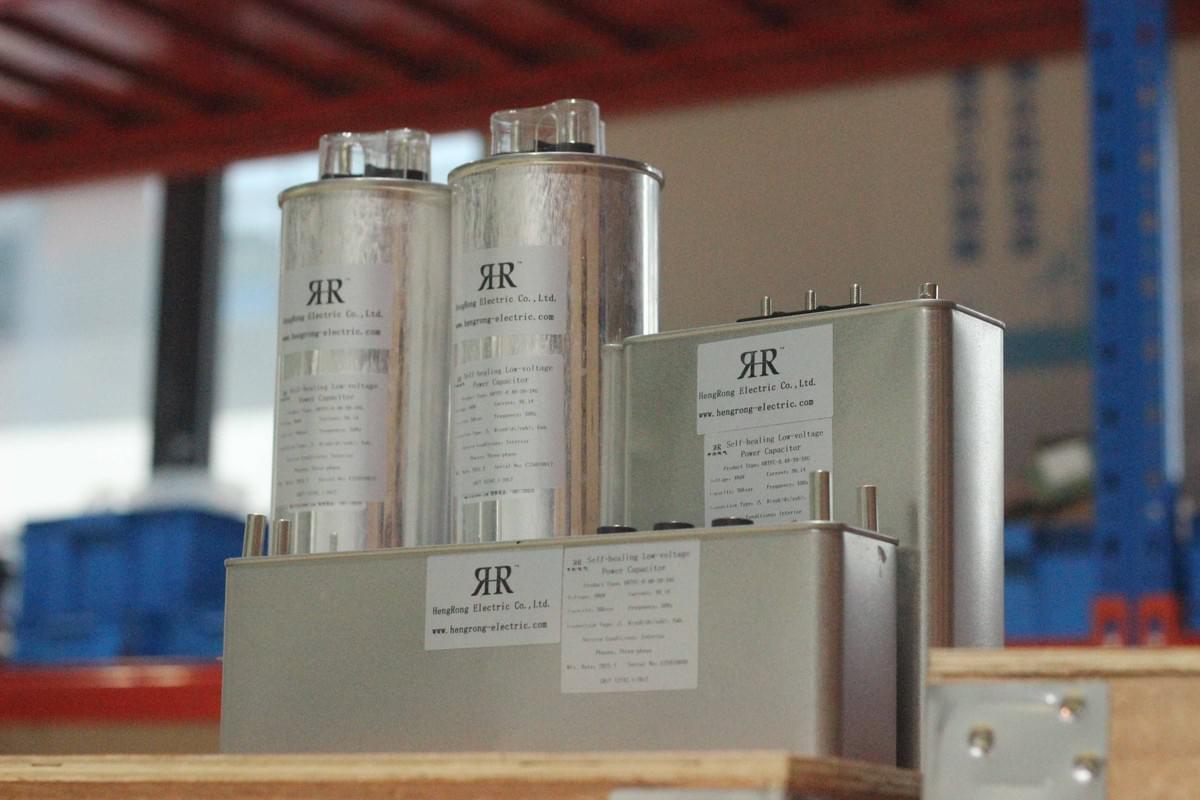
In modern power grid construction, reactive power compensation capacitors, as core equipment for improving the power factor of power grids and ensuring the stable operation of power systems, their reliability directly determines the safety and economic efficiency of power grids. With the continuous expansion of power grid scale, the rationality of installing and designing reactive power compensation capacitors, the timeliness of fault prevention, and the professionalism of daily operation & maintenance have become key issues of concern in the power industry. This article provides comprehensive and practical technical references from three key aspects: installation and design considerations for reactive power compensation capacitors, analysis of common faults, and targeted prevention and control measures.
I. Installation and Design of Reactive Power Compensation Capacitors: Laying the Foundation for Stable Operation
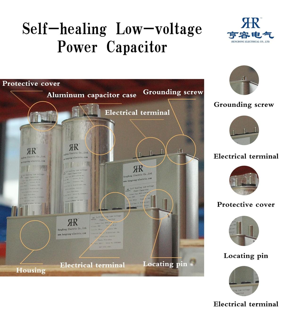
1. Control the Number of Capacitors per Group and Select a Reasonable Wiring Method
2. Configure Specialized Protection Components
3. Independent Erection to Avoid Interference from Shared Equipment
4. Design the Grounding Grid According to Capacity
- When the capacity of the capacitor is below 150 kvar, a set of grounding grids shall be laid in a ring around the rack, and the grounding resistance shall not exceed 50/IC Ω;
- When the capacity of the capacitor exceeds 150 kvar, to avoid being in a state of high resistance for a long time, it is necessary to adopt phase C grounding to erect a pseudo-three-phase line in the two-wire one-ground system, set up two sets of grounding grids, and ground from both ends of phase C. The double grounding design improves safety.
II. Common Faults of Reactive Power Compensation Capacitors: Identifying Risks for Accurate Response
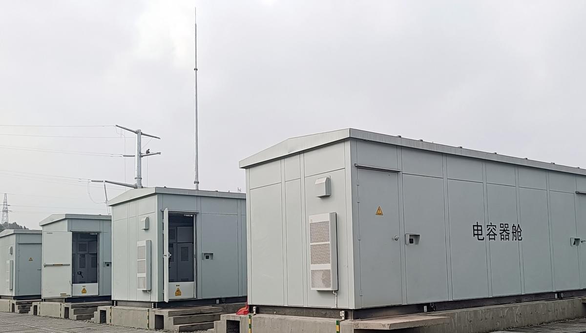
1. Capacitor Damage Fault: The Most Frequent Core Problem
- The quality of the compensation controller is unqualified, leading to incorrect switching (switching in or out by mistake) of the capacitor. Frequent starting and stopping cause loss of internal components.
- The inrush current during the instantaneous switching of compensation is too large, exceeding the tolerance range of the capacitor, resulting in damage to the internal insulation layer.
- The power grid voltage and three-phase current are unbalanced for a long time, causing local overload of the capacitor and accelerating the aging of components.
- The switching time of the compensation controller is set too short, leading to voltage superposition and generating an instantaneous high voltage that impacts the capacitor.
- Interference from high-order harmonics in the power grid distorts the current waveform of the capacitor and increases the risk of overcurrent.
2. Capacitor Harmonic and Harmonic Overcurrent Faults: Invisible Performance Killers
3. Capacitor Reactive Power Backflow Fault: Increasing the Operation Burden of the Power Grid
III. Prevention and Control Measures for Reactive Power Compensation Capacitor Faults: Comprehensive Guarantee for Reliable Equipment Operation
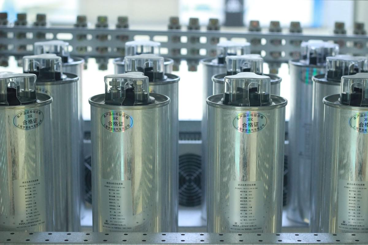
1. Accurate Prevention and Control of Capacitor Damage: Avoiding Risks from the Source
- Strict selection: Give priority to compensation controllers with qualified quality and stable performance to avoid incorrect operation of capacitors due to controller faults.
- Inrush current suppression: Connect reactors and other components in series in the circuit to effectively reduce the inrush current during the instantaneous switching of compensation and protect the internal structure of the capacitor.
- Parameter balancing: Regularly monitor the power grid voltage and three-phase current. Once a single-phase open circuit or parameter imbalance is found, immediately investigate the cause and repair it to ensure that the capacitor operates under balanced working conditions.
- Optimization of switching: Reasonably set the switching time of the compensation controller to avoid voltage superposition; If the compensation capacity is insufficient or the switching is frequent, the operation stability can be improved by increasing the compensation capacity and combining centralized compensation with local compensation.
- Harmonic interference resistance: Install anti-harmonic components or filtering devices in the power grid with harmonics to reduce the impact of harmonics on capacitors.
2. Special Solution to Harmonic Problems: Protecting Capacitor Performance
3. Strengthen Daily Inspection and Operation & Maintenance: Timely Detection of Potential Hidden Dangers
- Regular inspection: Monitor the operation status of the capacitor in real time, focusing on checking whether the shell has bulging or leakage, whether the wiring is firm, and whether there is debris and dirt accumulated on the surface.
- Timely maintenance: Once the above abnormalities are found, shut down the machine for maintenance immediately to avoid the expansion of faults leading to economic losses or personal injuries.
- Temperature control: Strictly control the operating temperature of the capacitor below 60℃. Excessively high temperatures will accelerate insulation aging and shorten the service life of the capacitor. Measures such as installing heat dissipation devices can be used to maintain a stable temperature.
Conclusion: Ensuring the Reliable Operation of Reactive Power Compensation Capacitors with Professional Management
